
 Contact Us
 Home / /


Stainless Steel Flanged Hub for Resonance Damper Shaft Assembly
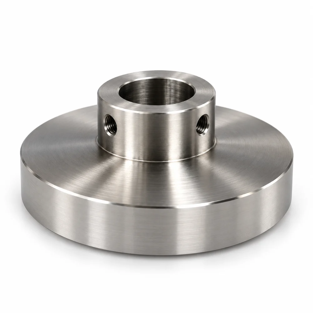
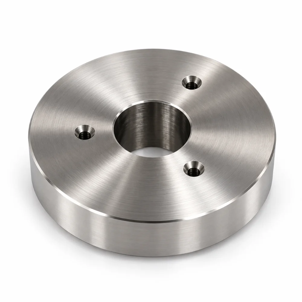
The Stainless Steel Flanged Hub is a custom precision part manufactured from AISI 316L stainless steel for an assembly to be used as a resonating damper. It is circular with a stepped central bore, three face holes evenly spaced around, a raised cylindrical hub, and two radial threaded holes.
According to the engineering drawing, one bore is identified as Ø0.500″ plus 0.0005″ but minus 0.0000″, and the other bore it has is identified as Ø0.750″ with dimensional tolerances. Bore geometry, alignment and machining stability are all critical considerations for such features.
-
Product Name: Custom Stainless Steel Flanged Hub
-
Drawing Description: Resonance Damper Shaft
-
Material: AISI 316L Stainless Steel
-
Manufacturing Process: Precision CNC Turning, Drilling and Tapping
-
Flange Diameter: Ø1.750″ (44.45 mm)
-
Overall Length: 0.790″ (20.07 mm)
-
Precision Hub Diameter: Ø0.750″ +0.0003″/−0.0011″
-
Precision Bore: Ø0.500″ +0.0005″/−0.0000″
-
Face Hole Pattern: Three Holes at 120° Intervals
-
Radial Threads: 2 × 6-32 UNC Through Threads
-
Material Finish: Machined Stainless Steel
-
Production Type: Custom Drawing-Based CNC Machining
 Get Free Quote


Precision CNC Turning of a 316L Flanged Hub
The component combines two different cylindrical diameters within a single machined structure.
The wide flange provides a circular mounting interface, while the raised hub contains the central opening and radial threaded features.
Unlike a simple spacer, the part requires multiple machining operations to establish its outer profile, stepped bore, and accurately positioned holes.
Controlling the Flange and Hub Geometry
The engineering drawing specifies a flange diameter of Ø1.750″ and an overall length of 0.790″.
The raised cylindrical section has a nominal diameter of Ø0.750″ with an asymmetric tolerance of +0.0003″/−0.0011″.
For similar components, maintaining a consistent relationship between the flange and hub is important for correct assembly.
A suitable CNC turning strategy should consider:
- Consistent flange and hub diameters
- Controlled shoulder transitions
- Alignment of cylindrical features
- Face geometry and finished thickness
- Stable workholding during turning
Karry Precision's CNC turning services support components with stepped profiles, controlled diameters, and custom assembly features.
Precision Machining of the Stepped Central Bore
One of the most demanding features is the stepped central opening.
The drawing identifies two nominal bore diameters:
- Ø0.450″ for one section of the internal profile
- Ø0.500″ with a tolerance of +0.0005″/−0.0000″ for the precision section
The second requirement creates a narrow allowable diameter range and requires an appropriate finishing and inspection strategy.
For 316L stainless steel, careful cutting-tool selection is important because the material can work-harden during machining.
The bore machining plan should consider finishing allowances, cutting conditions, and tool wear.
The intended bore fit and functional requirements must follow the approved assembly drawing.
Three-Hole Flange Pattern and Radial Threading
The hub includes additional holes that require machining from different directions.
These features distinguish the project from a conventional CNC turned cylindrical part.
Three Equally Spaced Face Holes
The circular flange contains three small holes positioned at 120° intervals.
According to the drawing, each hole has a nominal diameter of Ø0.089″ and a depth of 0.125″, with an associated Ø0.109″ × 90° entrance feature.
The hole centers lie on a nominal radius of 0.463″ from the component center.
Machining these features requires attention to angular indexing, drilling depth, and the relationship between the hole pattern and the central bore.
Radial 6-32 UNC Threaded Holes
The raised hub includes two radial holes specified as 6-32 UNC through threads.
These are different from the three smaller holes on the flange face.
For similar components, radial threading involves positioning the cylindrical workpiece, drilling from the sidewall, and producing the required thread geometry.
Important manufacturing considerations include thread alignment, engagement with the mating fastener, and removing burrs where the radial holes intersect the internal bore.
Appropriate thread gauges should be selected according to the complete drawing requirements.
Why Use AISI 316L Stainless Steel?
316L stainless steel provides good corrosion resistance, including improved resistance to certain chloride-containing environments compared with standard 304 stainless steel.
It is commonly used for engineered components that require corrosion resistance and suitable mechanical properties.
For this flanged hub, 316L also introduces machining considerations.
Its tendency to work-harden requires controlled cutting conditions, appropriate tools, and attention to heat generation.
The material's suitability for the actual resonance damper assembly depends on its mechanical loading, environmental conditions, and the complete equipment design.
Detailed Technical Specifications
| Parameter | Specification |
|---|---|
| Product | Stainless Steel Flanged Hub |
| Drawing Name | Resonance Damper Shaft |
| Material | AISI Type 316L Stainless Steel |
| Main Process | CNC Turning |
| Additional Operations | Drilling, Boring and Tapping |
| Flange Diameter | Ø1.750″ |
| Overall Length | 0.790″ |
| Flange Thickness | 0.441″ |
| Hub Diameter | Ø0.750″ +0.0003″/−0.0011″ |
| Precision Bore | Ø0.500″ +0.0005″/−0.0000″ |
| Additional Bore | Ø0.450″ |
| Face Hole Pattern | 3 × Ø0.089″, 0.125″ Deep |
| Hole Entrance | Ø0.109″ × 90° |
| Angular Arrangement | 120° Typical |
| Radial Threads | 2 × 6-32 UNC THRU |
| Typical Chamfer | 0.010″ × 45° |
| Surface Finish | Machined Finish |
| Inspection Basis | Customer Engineering Drawing |
The dimensional values are engineering drawing requirements, not independently verified measurements. Specific dimensional callouts take precedence over general tolerances.
Quality Control for Precision Machined Flanged Hubs
Dimensional inspection is especially important when a component combines tight bore tolerances, a circular hole pattern, and radial threaded features.
The inspection plan should distinguish between general dimensions and the individual precision requirements identified on the drawing.
| Inspection Feature | Quality Control Focus |
|---|---|
| Flange Diameter | External diameter and circular geometry |
| Raised Hub | Diameter and relationship to the flange |
| Precision Bore | Ø0.500″ tolerance verification |
| Stepped Internal Profile | Bore size and transition geometry |
| Three Face Holes | Position, angular spacing and drilling depth |
| Radial Threads | 6-32 UNC thread condition and fit |
| Finished Faces | Surface condition and applicable dimensional requirements |
Depending on the relevant tolerances, suitable inspection equipment may include bore gauges, micrometers, height gauges, coordinate measuring machines, and thread gauges.
Where concentricity or runout requirements apply, their acceptance criteria must be established from the complete approved drawing.
Karry Precision provides additional information on its tolerance and quality control capabilities.
Application in a Resonance Damper Shaft Assembly
The customer drawing identifies the component as a Resonance Damper Shaft.
The flange, central bore, and radial threads provide several possible mechanical interfaces within the assembly.
For similar components, the flange may serve as a mounting surface, while the central bore and radial threaded holes may interact with a mating shaft or fastening elements.
The exact function of these features must be confirmed from the complete assembly design.
The supplied documentation does not provide operational vibration measurements, rotational speed ratings, or verified damping performance.
Therefore, this case focuses on the component's manufacturing requirements rather than claiming specific system performance.
Frequently Asked Questions
What is a stainless steel flanged hub?
A stainless steel flanged hub is a circular mechanical component combining a flange with a raised cylindrical section. Depending on its design, it may include central bores, mounting holes, and threaded features for assembly.
Why is 316L stainless steel used for this component?
316L stainless steel offers good corrosion resistance and useful mechanical properties. It can be machined into precision components when suitable cutting conditions and manufacturing methods are selected.
Can CNC turning produce precision stepped bores?
Yes. CNC turning and boring operations can manufacture stepped internal profiles. Actual achievable accuracy depends on the bore size, tolerance requirements, tooling, workholding, and inspection method.
How are three equally spaced holes machined on a flange?
CNC drilling or milling equipment with suitable positioning or indexing can produce hole patterns at specified angular intervals. Hole dimensions and locations must follow the engineering drawing.
What are radial 6-32 UNC threaded holes?
They are threaded holes extending from the cylindrical side surface toward the interior of the component. A 6-32 UNC thread is an inch-series fastener thread with 32 threads per inch.
Can Karry Precision manufacture custom stainless steel flanged hubs?
Karry Precision provides custom CNC machining services for flanges, hubs, shafts, and other precision metal parts. Customers can submit engineering drawings to review material requirements, tolerances, machining feasibility, inspection needs, and quotations.




