
 Contact Us
  Home /
Precision Machined Components for Robotics & Automation
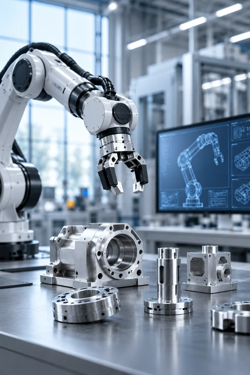
Custom CNC machining for robotic joints, housings, brackets, shafts and motion-control components. Karry Precision supports prototype development, low-volume builds and repeat production from customer drawings.
 Get Free Quote
Robotics
ROBOTICS MANUFACTURING
Precision CNC Components for Robotics & Automation
Robotic systems depend on accurate alignment, repeatable motion and components that fit together without unnecessary play or interference. Karry Precision manufactures custom CNC parts from customer drawings for robot joints, drive assemblies, end-effectors, housings, brackets and other precision mechanical structures.
- Prototype, low-volume and repeat production support
- 3-axis, 4-axis and simultaneous 5-axis CNC machining
- Metals and engineering plastics for motion and structural parts
- Inspection planned around functional and mating features
What Matters in Robotic Mechanical Components
The best machining strategy starts with the interfaces that influence motion, alignment, weight and service life.
01 · MOTION ACCURACY
Motion Alignment
Critical bores, shafts, bearing seats and mounting datums should stay in controlled relationship to support smooth and repeatable movement.
02 · LIGHTER AXES
Low Moving Mass
Material choice and pocketed geometries can reduce moving weight while maintaining the stiffness required by robotic structures.
03 · BUILD CONSISTENCY
Repeatable Assembly
Locating faces, hole patterns and mating interfaces should support consistent assembly across prototypes and repeat production builds.
04 · LONGER SERVICE LIFE
Wear & Service Life
Fit, material and surface condition should be considered together for joints, guides, bushings and transmission components.
Manufacturing Capabilities for Robotics Projects
Select the machining route around geometry, functional features, production volume and inspection requirements rather than forcing every component into one process.
01 · PRISMATIC PARTS
CNC Milling
For housings, brackets, mounting plates, frames, fixtures and multi-face mechanical components.
02 · ROTATIONAL PARTS
CNC Turning
For shafts, pins, spacers, sleeves, bushings and other rotational components with controlled diameters.
03 · COMPLEX GEOMETRY
5-Axis CNC Machining
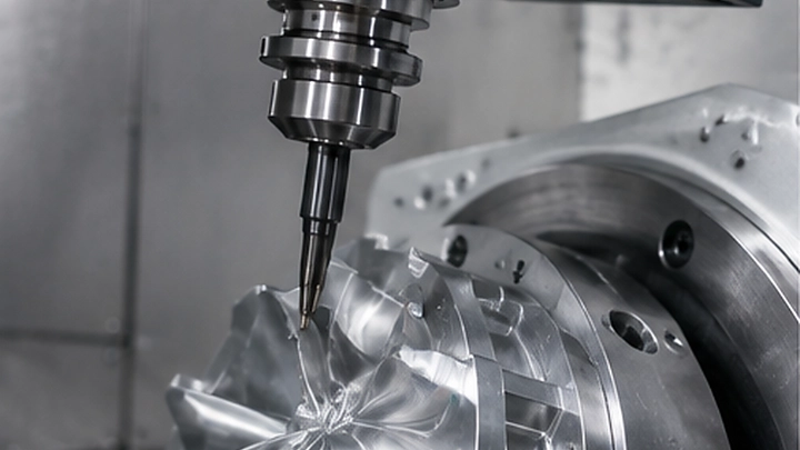
For complex joint bodies, compound angles, multi-surface features and components that benefit from fewer setups.
04 · PROJECT COMPLETION
Assembly & Finishing Support
Surface finishing and assembly services can be coordinated where projects require completed mechanical subcomponents.
TYPICAL ROBOTICS PART TYPES
Precision Parts for Motion, Mounting & Integration
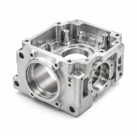
Joint & Gearbox Housings
Multi-face housings with bearing bores, mounting datums and internal interfaces.
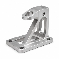
Motor & Structural Brackets
Rigid mounting structures for motors, sensors, linear modules and robotic frames.
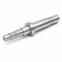
Drive Shafts & Pins
Turned components for rotational interfaces, pivots, couplings and transmission assemblies.
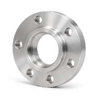
End-Effector Interfaces
Flanges, adapter plates and mounting interfaces for grippers, tooling and automation modules.
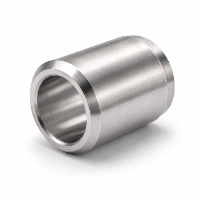
Bushings & Spacers
Precision cylindrical parts used to control fit, spacing, guidance and rotational interfaces.
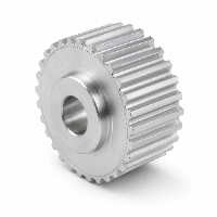
Pulleys & Drive Parts
Custom transmission parts for belt-driven, rotary and motion-control mechanisms.
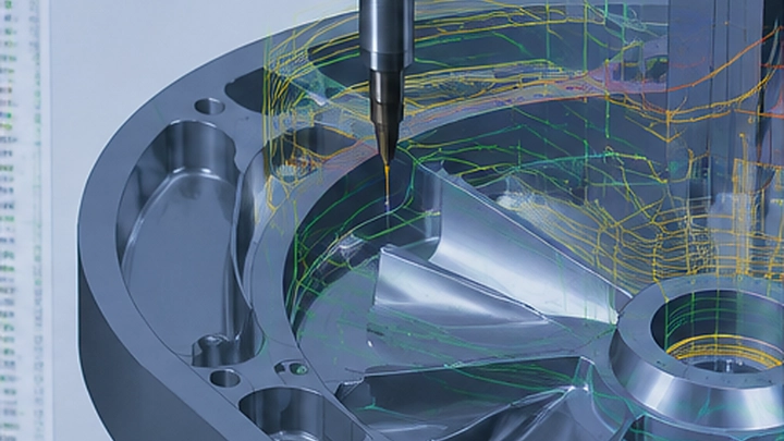
ENGINEERING FOCUS
Control the Interfaces That Affect Robotic Motion
A robotics component can meet its overall dimensions and still create assembly or motion problems if the critical relationships are not controlled. Drawing review should identify the features that influence positioning, bearing fit, drive alignment and tool mounting.
- Bearing and shaft interfaces: bore size, coaxiality, roundness and surface condition
- Motor and gearbox mounting: datum control, hole position and face perpendicularity
- End-effector interfaces: repeatable hole patterns, locating features and mounting faces
- Lightweight structures: pocketing, thin walls and stiffness balanced against distortion risk
Materials for Robotics CNC Machining
Material selection should reflect stiffness, weight, wear, friction, corrosion resistance, operating temperature and the required manufacturing process.
| Material Family | Useful Properties for Robotics | Typical Robotics Applications |
|---|---|---|
| Aluminum | Lightweight, machinable, corrosion resistant | Robot frames, brackets, housings, end-effector plates |
| Stainless Steel | Strength, corrosion resistance, durability | Shafts, precision interfaces, fasteners, exposed components |
| Alloy / Carbon Steel | High strength, toughness and wear performance | Drive components, shafts, structural and load-bearing parts |
| POM / Acetal | Low friction, dimensional stability, wear resistance | Precision gears, sliding parts, bushings and guides |
| Nylon | Wear resistance, toughness, fatigue resistance | Pulleys, rollers, cams, guides and spacers |
| PEEK / High-Performance Plastics | Heat resistance, chemical resistance, dimensional stability | Selected high-performance mechanical or insulating components |
Surface Finishes for Robotic Components
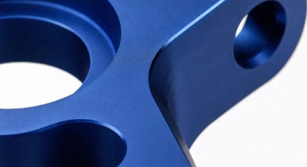
Anodizing
Useful for aluminum parts requiring improved corrosion resistance, surface hardness or functional color identification.
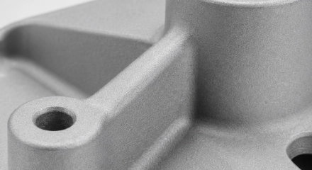
Bead Blasting
Creates a uniform matte surface and helps reduce visible machining marks on selected aluminum, stainless steel and titanium components.
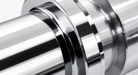
Polishing
Reduces surface roughness and creates a smoother finish for selected shafts, interfaces and other precision metal components.
TOLERANCE & QUALITY CONTROL
Inspection Planned Around Fit, Position & Repeatability
Robotics drawings often contain a mix of general dimensions and a smaller number of function-critical features. Karry Precision evaluates tolerance requirements according to geometry, material, process and inspection conditions rather than applying unnecessarily tight tolerances to every dimension.
- Typical CNC machining reference: around ±0.05 mm
- Selected precision features can be reviewed for tighter control
- CMM and other precision measurement methods for complex feature relationships
- ISO 9001-certified quality processes and pre-shipment inspection
Quality Focus for Robotics Parts
01 · Datum relationships
Mounting faces, bores and locating features.
02 · Hole position & alignment
Motor, sensor, bearing and tooling interfaces.
03 · Fits & rotating features
Shafts, bushings, bearings and coupling features.
04 · Repeat production
Controlled setups and inspection for part-to-part consistency.
From Robotics Prototype to Repeat Production
A six-step workflow keeps the project easy to review and each stage can be adjusted to the part, quantity and documentation requirements.
STEP 01
Drawing Review
Review CAD, drawings, quantities, material and critical functional features.
STEP 02
DFM & Process Planning
Select machining route, setups, workholding and practical tolerance strategy.
STEP 03
Material & Setup
Prepare material, tooling, CNC programs and inspection references.
STEP 04
Precision Machining
Mill, turn or 5-axis machine the component using the planned process route.
STEP 05
Inspection & Finishing
Verify critical dimensions and complete required surface finishing operations.
STEP 06
Final Verification & Delivery
Complete final checks, packaging and shipment for prototype or repeat production orders.
Why Robotics Teams Work with Karry Precision
DFM Support
Engineering review before machining to identify process, access and tolerance risks.
Complex Machining
3-, 4- and 5-axis machining for multi-face and geometry-intensive robotic components.
Controlled Quality
ISO 9001-certified processes with in-process and final dimensional verification.
Flexible Production
Support from one-off prototypes through low-volume and repeat production requirements.
Ready to Review Your Robotics Part?
Send the 2D drawing or 3D model with material, quantity, finish and critical requirements.
Robotics CNC Machining FAQ
What robotics parts can Karry Precision machine?
Typical CNC part types include housings, brackets, shafts, flanges, bushings, pulleys, fixtures and custom mechanical components. Final process selection depends on the drawing, material, tolerance and quantity.
Can you machine complex robot joint or multi-face components?
Yes. Karry Precision offers 3-axis, 4-axis and simultaneous 5-axis CNC machining. Multi-axis machining can reduce repeated setups for parts with angled, curved or multi-face features.
What tolerances are suitable for robotics components?
Standard CNC machining is typically around ±0.05 mm, while selected critical features may be reviewed for tighter control. The achievable tolerance depends on material, geometry, feature size, machining access and inspection requirements.
Which materials are commonly suitable for robotic parts?
Aluminum, stainless steel, alloy steel, POM, nylon and other engineering plastics are common options. Material choice should be based on weight, stiffness, wear, friction, environment and service conditions.
Can you support robotics prototypes before production?
Yes. Karry Precision supports prototype and low-volume CNC machining as well as repeat production. Drawings can be reviewed before machining to identify manufacturability and tolerance risks.
What information should I send for a robotics machining quote?
Send the 2D drawing or 3D model together with material, quantity, surface finish and required tolerances. Identify critical mating, positioning or motion-related dimensions so the engineering team can review them properly.