
 Contact Us
 Home /

CNC Machining Tolerancese & Quality Control
Karry Precision is a custom precision parts CNC machining shop with dimensional control and inspection. Tolerances for common machined components, or special tolerances for specific features and intentions, are considered together with material selection, geometry and functional discussions as well as inspection methods, both for prototype and repeat production, to ensure reliable results.
 Get Free Quote


Tolerance and Quality Control
Why CNC Machining Tolerances Matter
A tolerance defines the acceptable dimensional variation of a manufactured feature, but its real purpose is to protect part function. Effective tolerance control focuses on the dimensions that influence assembly, movement, sealing, positioning, and long-term performance—not simply making every dimension as tight as possible.
1. Functional Fit & Assembly
Mating features such as shafts, bores, locating surfaces, threads, and mounting interfaces must work together within a controlled dimensional range.Appropriate tolerances help reduce unwanted clearance, interference, misalignment, and assembly difficulty while supporting reliable part-to-part fit.
2. Functional Performance
Small dimensional variations can affect friction, movement, sealing, vibration, positioning, and load distribution.Controlling function-critical features helps machined components perform consistently after they are installed in the final product or assembly.
3. Tolerance & Manufacturing Cost
The tighter a tolerance becomes, the more demanding the machining and inspection process may be.By identifying critical dimensions early, tighter controls can be applied where function requires them while practical tolerances are maintained on non-critical features. This creates a better balance between performance and manufacturing cost.
4. Production Repeatability
A successful precision part must be repeatable—not accurate only once.Stable setups, controlled tooling, consistent machining parameters, and defined inspection methods help maintain dimensional consistency when moving from prototypes to low-volume and repeat production.
What Affects CNC Machining Tolerances?
Tolerance capability is the result of the complete manufacturing process. Material response, machine condition, cutting strategy, geometry, workholding, and temperature can all influence the final dimensions of a CNC-machined part.
Material Stability
Different materials react differently to cutting forces, heat, and stress release.
Material hardness, thermal expansion, rigidity, and internal stress must therefore be considered when selecting machining strategies for tight-tolerance features.
Machine Capability
Machine rigidity, positioning accuracy, spindle condition, and repeatability influence how consistently dimensions can be maintained.
The appropriate equipment should be selected according to the geometry and accuracy requirements of each component.
Cutting Tool Performance
Tool geometry, tool wear, cutting parameters, and finishing allowance all affect dimensional stability.
Monitoring tool condition is particularly important during repeat production because gradual wear can cause dimensions to drift over time.
Part Geometry
Thin walls, deep pockets, long slender features, small holes, and complex multi-face structures can be more sensitive to cutting forces and deformation.
These features often require customized machining sequences rather than a standard approach.
Workholding Stability
A part must be located securely and repeatably without being distorted by excessive clamping force.
Proper fixture design helps maintain datum relationships and reduces positioning variation between machining operations.
Thermal & Measurement Conditions
Temperature affects machine structures, cutting tools, workpieces, and measurement results.
For tighter tolerance requirements, dimensional verification should be performed using appropriate measuring equipment under stable conditions.
Reliable precision comes from controlling these variables as a connected process. Karry Precision evaluates machining strategy, tooling, workholding, material behavior, and inspection requirements together instead of relying on final inspection alone.
CNC Machining Tolerance Capabilities
Achievable CNC machining tolerances depend on material, part geometry, feature size, machining method, workholding, and inspection requirements. The following values are based on Karry Precision's currently published machining references. Critical dimensions and tighter tolerances require engineering review before production.
| Process / Service | General / Typical Capability | Precision / Critical Capability | Notes |
|---|---|---|---|
| CNC Machining | ±0.10 mm | ±0.05 mm precision; ±0.02–0.03 mm high precision; selected critical features down to ±0.01 mm | Depends on material, geometry, feature size, setup and inspection |
| 5-Axis CNC Machining | ±0.05 mm | ±0.02–0.05 mm precision; selected high-precision features ±0.01–0.02 mm | Complex surfaces and feature relationships require engineering review |
| Sheet Metal Fabrication | ±0.10–0.20 mm for cut features | Hole diameter ±0.10 mm; bend angle ±0.5° | Depends on material thickness, cutting method and bend geometry |
| Die Casting | ±0.10–0.50 mm as-cast | ±0.10–0.30 mm for selected high-precision cast features | Tighter critical dimensions may require secondary CNC machining |
| Plastic Injection Molding | ±0.20–0.30 mm | ±0.10–0.20 mm precision; critical mating features ±0.05–0.10 mm | Depends on resin shrinkage, geometry, wall thickness and mold design |
| Metal Stamping Parts | Project dependent | Selected critical features down to ±0.10 mm | Depends on material thickness, geometry and tooling |
| Metal Stamping Tooling | ±0.01–0.10 mm for tooling features | Feature-specific | Refers to die components, not finished stamped-part tolerance |
Tighter tolerances are not automatically suitable for every feature. For precision projects, we recommend reviewing the drawing first to determine which dimensions require enhanced process and inspection control.
Precision Control from Material to Finished Part
-
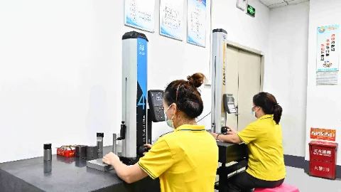 Critical dimensions are checked using precision measuring equipment to verify that machined parts meet drawing and tolerance requirements.
-
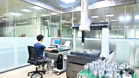 Coordinate measuring equipment is used to inspect complex geometries, hole positions, feature relationships, and other critical dimensions with high repeatability.
-
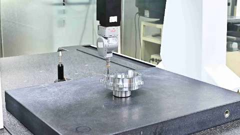 Components are inspected on a precision granite surface plate to verify height, flatness, position, and other dimensional features.
-
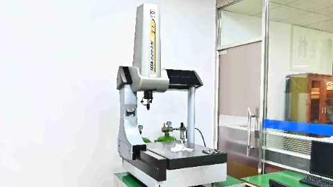 Precision measurement is used to evaluate dimensional and geometric requirements such as position, perpendicularity, and feature alignment.
-
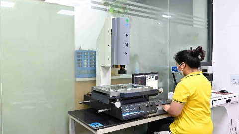 Optical measuring equipment is used for small features, profiles, edges, and dimensions where non-contact inspection provides better visibility and accuracy.
-
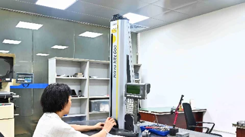 Precision height measuring systems help verify part heights, steps, reference surfaces, and positional relationships against engineering drawings.
-
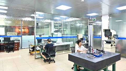 Key dimensions are checked during production so machining variation can be identified and corrected before final inspection.
-
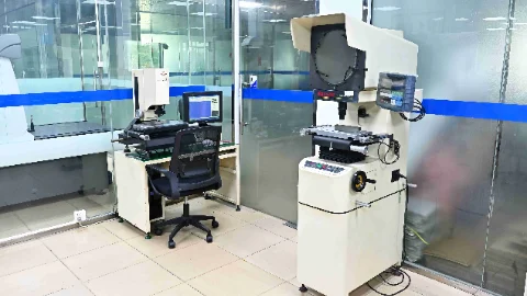 Vision measurement systems provide accurate non-contact inspection for small, detailed, or complex component features.
-
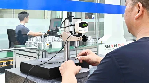 Magnification equipment is used to examine small features, edges, surface conditions, burrs, and other details that may be difficult to evaluate by eye alone.
-
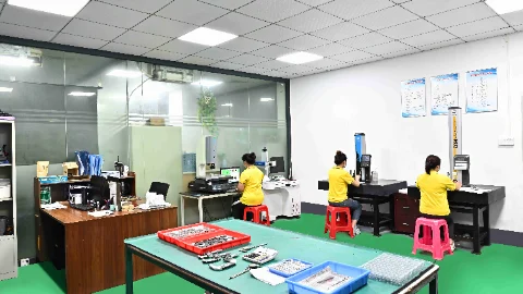 Finished parts undergo final dimensional and visual checks before shipment to confirm that critical requirements have been met.
CNC Machining Tolerances FAQs





