
 Contact Us
 Home / /


Stainless Steel Fixture Plate for Precision Catheter Pathway Sizing
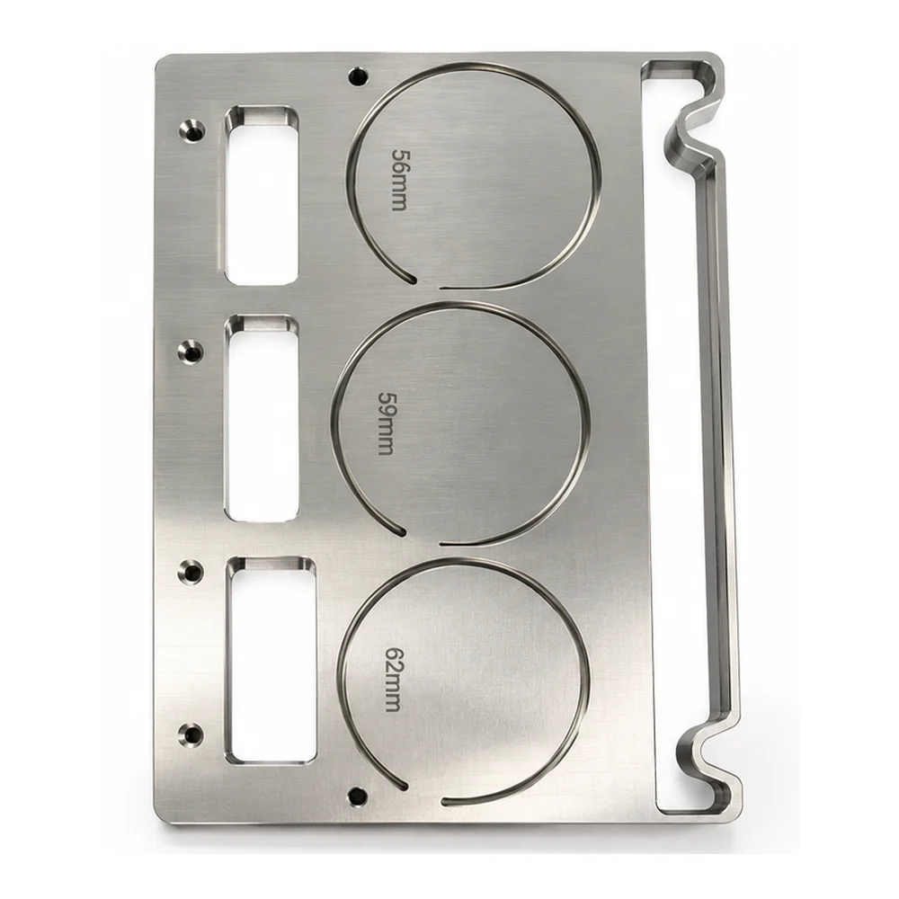
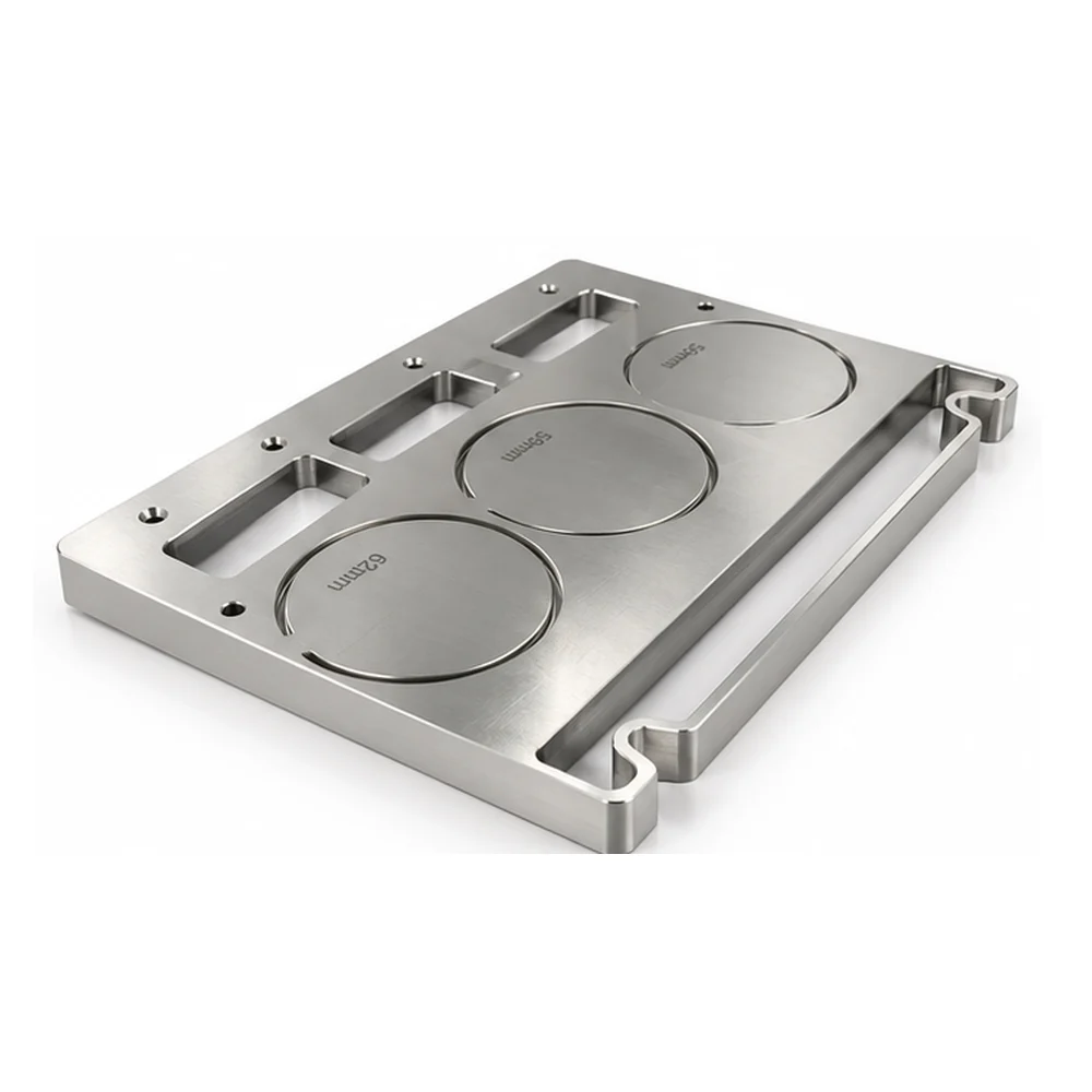
This Stainless Steel Fixture Plate is a custom CNC machined component designed with three curved guide profiles, rectangular openings, and precision mounting features for controlled positioning and component fit.
Manufactured from SUS304 stainless steel, the plate incorporates three individually marked guide sizes of 56 mm, 59 mm, and 62 mm. Its thin, flat construction requires careful machining of curved contours, narrow features, and fastening holes while maintaining dimensional accuracy across the entire plate.
-
Product Name: Stainless Steel Fixture Plate
-
Material: SUS304 / AISI 304 Stainless Steel
-
Overall Dimensions: 203.2 × 120.65 × 3.18 mm
-
Manufacturing Process: CNC Milling, Precision Slotting, Drilling and Marking
-
Guide Size Markings: 56 mm / 59 mm / 62 mm
-
Surface Treatment: Passivation per ASTM A967
-
Application: Catheter Pathway Sizing and Precision Fixture Assembly
-
Production Type: Custom Precision CNC Machined Parts
 Get Free Quote


Three Guide Sizes, One Stainless Steel Fixture Plate
A distinctive feature of this component is its arrangement of three curved sizing profiles on a single stainless steel plate.
Rather than using three separate fixtures, the design integrates the 56 mm, 59 mm, and 62 mm guide positions within one continuous structure. Each position includes a curved contour, an adjacent rectangular opening, and a clearly identified size marking.
The drawing specifies a slip fit with a catheter, making the geometry and edge condition of the relevant guide features especially important.
This integrated configuration provides several practical design advantages:
- Three separately identified guide sizes within one plate.
- Curved profiles arranged for consistent positioning.
- Rectangular openings incorporated alongside each guide position.
- A common mounting structure that maintains the relationship between the three profiles.
- Permanent size identification to distinguish the individual guide positions.
The purpose of CNC machining in this project is not simply to reproduce a rectangular plate. It is to maintain the functional relationship between the curved pathways, openings, mounting locations, and finished plate surfaces.
Machining the Curved Pathways Without Compromising the Plate
The most demanding part of this design is the combination of multiple curved features and a relatively thin stainless steel body.
At a nominal thickness of only 3.18 mm, the plate needs controlled workholding during material removal. Excessive clamping pressure or cutting forces can introduce distortion, affecting the alignment of features across the finished surface.
Controlling Thin-Plate Distortion
For a component of this geometry, machining strategy should prioritize stable support and balanced material removal.
Suitable fixtures help distribute holding forces across the plate. Finishing operations can then be planned to reduce the risk of bending or localized deformation around the machined openings.
Maintaining the Three Curved Profiles
The three curved guide features differ in their designated sizes but share a similar layout.
Consistent tool engagement, suitable cutter selection, and controlled finishing passes are important for maintaining their intended shapes.
Particular attention is needed at the open ends of each curved feature, where small remaining sections and local transitions can be more susceptible to burr formation.
Machining Rectangular Openings and Mounting Features
The design also includes three rectangular through-openings and several smaller mounting holes.
These features require accurate positioning relative to the guide profiles and external plate boundaries. CNC milling and drilling are suitable for producing the openings while controlling corner geometry and edge quality.
The specified threaded features and close-tolerance holes must be verified against their individual drawing requirements rather than relying only on general dimensional tolerances.
Detailed Technical Specifications
| Parameter | Specification |
|---|---|
| Product Name | Stainless Steel Fixture Plate |
| Drawing Description | Pathway Shape Set Plate Assembly, VTK |
| Material | SUS304 / AISI 304 Stainless Steel |
| Overall Dimensions | 203.2 × 120.65 × 3.18 mm |
| Nominal Plate Thickness | 0.125 in (3.175 mm) |
| Thickness Tolerance | ±0.002 in (±0.0508 mm) |
| Manufacturing Process | CNC Milling, Slotting, Drilling and Marking |
| Guide Size Markings | 56 mm / 59 mm / 62 mm |
| Rectangular Openings | 3 |
| Precision Through-Hole Callout | Ø0.1260 ±0.0005 in |
| Thread Specification | 10-32 UNF THRU, as individually called out |
| Unspecified Dimension Tolerance | ±0.005 in (±0.127 mm) |
| Additional Flatness Callout | 0.003 in (0.0762 mm) |
| Surface Finish Reference | 125 µin / 3.2 µm Ra |
| Edge Break Requirement | 0.010 in maximum unless otherwise specified |
| Surface Treatment | Passivation per ASTM A967 |
| Size Identification | Scribed markings, 16-point font |
| Inspection | Drawing-Based Dimensional, Profile and Surface Inspection |
Note: Specific feature tolerances and geometric requirements take precedence over general drawing tolerances. The 56 mm, 59 mm, and 62 mm values are identified guide sizes and should not automatically be interpreted as measured groove diameters.
Where Inspection Matters Most
For this fixture plate, inspection involves more than checking the overall length and width.
The three guide positions must remain correctly arranged relative to the rectangular openings and mounting features. Flatness also matters because the component is designed to operate as a single thin plate.
The inspection approach therefore focuses on three areas.
1. Guide Profile Geometry
The curved features should be checked against the approved profile geometry, including their positions, transitions, and open ends. Size markings must correspond to the correct guide locations.
2. Plate Flatness and Feature Positioning
Flatness inspection helps identify distortion introduced during machining or finishing. Through-hole locations and the three rectangular openings require dimensional verification against the drawing.
3. Edge Condition and Surface Quality
The drawing requires removal of burrs and sharp edges, with a maximum edge break of 0.010 in unless otherwise specified.
This is particularly relevant around the curved guide profiles, rectangular openings, and smaller mounting holes. Deburring must not unintentionally enlarge or deform the functional openings.
Surface Finishing: Preserving Stainless Steel Functionality
SUS304 stainless steel provides useful corrosion resistance for precision mechanical components, but machining can introduce surface contamination and leave localized burrs.
For this project, the specified finishing approach is passivation according to ASTM A967.
Unlike decorative plating, passivation is intended to support stainless steel corrosion resistance without adding a substantial coating thickness.
The drawing also states that dimensional requirements apply after finishing. Therefore, final verification should consider the completed surface condition rather than machining dimensions alone.
Application in Specialized Fixture Assemblies
The drawing identifies the component as a pathway shape set plate and includes a catheter slip-fit requirement.
Its configuration is consistent with a specialized sizing, positioning, or handling fixture in which several guide profiles are required within a common mounting arrangement.
Similar CNC machined stainless steel plates can be engineered for medical-device manufacturing fixtures, laboratory equipment, dimensional checking tools, and precision assembly systems.
The component's actual suitability for a particular medical process depends on the complete assembly requirements, applicable material controls, and validation procedures.
What Makes This Stainless Steel Plate Different?
The defining characteristic of this project is the integration of three different curved guide sizes into a thin, single-piece stainless steel structure.
The engineering focus extends beyond general milling accuracy to include the relationship between guide contours, openings, flatness, permanent markings, and post-machining edge quality.
It illustrates how CNC machining can support specialized fixture geometry where multiple functional positions must be incorporated into one compact component.
Frequently Asked Questions
1. Why use stainless steel for a precision fixture plate?
SUS304 offers corrosion resistance, mechanical stability, and suitability for precision machining. It is useful for fixtures that require machined openings, repeatable positioning, and a durable metal structure.
2. Can multiple curved guide sizes be machined into one plate?
Yes. CNC milling can produce multiple curved profiles within a single component. The achievable geometry depends on material thickness, tool access, profile spacing, and specified tolerances.
3. How is distortion controlled when machining a 3.18 mm stainless steel plate?
Suitable workholding, balanced machining sequences, controlled cutting forces, and flatness inspection can help reduce distortion. The process should be selected according to the plate geometry and material condition.
4. Why are the 56 mm, 59 mm, and 62 mm markings important?
The markings identify the three individual guide positions and help distinguish the intended sizing configurations. The drawing calls for these identifiers to be scribed using a 16-point font.
5. Can custom fixture plates include different guide profiles and mounting arrangements?
Yes. Karry Precision can evaluate custom CNC machined fixture plate designs with application-specific contours, slots, drilled holes, threaded features, and finishing requirements.




