
 Contact Us
 Home / /
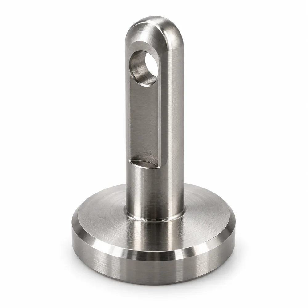
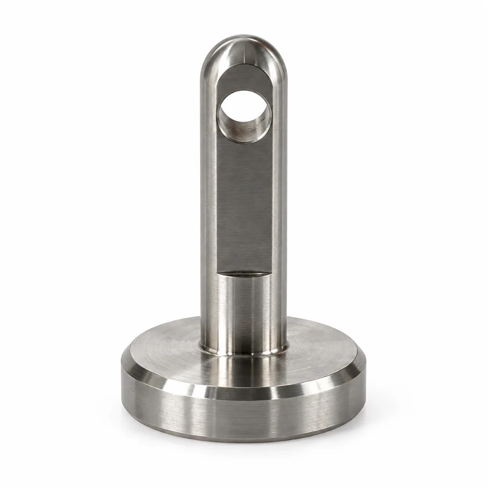
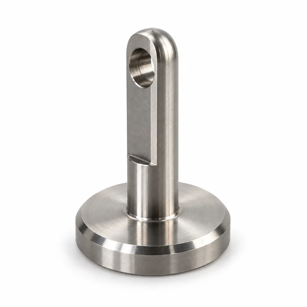


Stainless Steel Compression Plunger – Precision CNC Machined Component
This Stainless Steel Compression Plunger is a custom precision component manufactured according to detailed engineering specifications for a mechanical compression assembly.
Made from 300-series stainless steel, the part combines a circular mounting flange, a precision cylindrical shaft, a transverse hole, and a longitudinal machined relief. Its design requires careful control of shaft diameter, feature positioning, and alignment between the flange and the plunger body.
-
Product Name: Stainless Steel Compression Plunger
-
Material: 300-Series Stainless Steel
-
Manufacturing Process: CNC Turning, Milling and Precision Drilling
-
Overall Dimensions: Approximately 35.21 × 22.35 × 22.35 mm
-
Main Features: Circular Flange, Precision Shaft, Transverse Hole and Longitudinal Relief
-
Critical Shaft Tolerance: Ø0.3125″ h7 (+0 / −0.0006″)
-
Surface Roughness: Ra 3.2 µm
-
Production Type: Custom Precision Machined Component
 Get Free Quote


Understanding the Design of This Stainless Steel Compression Plunger
At first glance, this component resembles a simple flanged pin. However, the engineering drawing reveals several interacting features that make its manufacturing requirements more demanding than those of a conventional cylindrical pin.
The large circular flange forms a distinct shoulder at one end of the component, while the smaller shaft extends outward with a tightly controlled diameter. A transverse opening and a longitudinal relief introduce additional geometry into an otherwise rotationally symmetrical part.
These features cannot be considered independently during machining.
For example, the shaft diameter influences its fit within a mating bore, while the location of the transverse hole determines how it can interface with another mechanical element. The flange provides a reference surface that may influence the installed position of the component.
The manufacturing objective is therefore not simply to produce an accurate cylindrical shape. It is to preserve the intended geometric relationships between the shaft, flange, and machined openings.
From Cylindrical Stock to a Finished Plunger
Establishing the Flange and Shaft Geometry
The most practical starting point for this type of component is CNC turning.
Turning operations can establish the main shaft diameter, circular flange, shoulder transition, and specified edge chamfers while maintaining a common rotational reference.
One dimension requires particular attention: the shaft diameter of Ø0.3125″ with an h7 tolerance.
Unlike a general machining dimension, this specification defines a narrow permissible shaft size range. Excessive stock removal can create unwanted clearance, while an oversized shaft may prevent installation into its mating component.
For that reason, final shaft sizing should be planned around controlled finishing cuts and dimensional verification rather than relying exclusively on rough turning.
Adding the Cross-Hole and Longitudinal Relief
After the main cylindrical geometry is established, the non-round features require additional machining.
The engineering drawing includes a transverse hole with a diameter range of Ø0.189″ to Ø0.191″. It also shows a longitudinally machined region extending along part of the shaft.
These features introduce two specific manufacturing considerations.
First, the transverse hole must remain correctly positioned relative to the reference geometry.
The drawing includes a 0.010″ geometric position requirement associated with datum references A and B. Hole location must therefore be evaluated as a geometric relationship, not merely by checking the hole diameter.
Second, the machined relief must maintain the intended shaft profile.
Removing material from one side of a relatively small-diameter shaft changes the local cross-section. The machining setup should minimize unwanted movement or distortion while maintaining the specified relief geometry.
A suitable milling and drilling setup, supported by appropriate workholding, can help preserve these relationships.
Detailed Technical Specifications
| Parameter | Technical Specification |
|---|---|
| Product Name | Stainless Steel Compression Plunger |
| Drawing Description | Length Compression Plunger |
| Material | 300-Series Stainless Steel |
| Manufacturing Method | CNC Turning, Milling and Drilling |
| Overall Dimensions | Approx. 35.21 × 22.35 × 22.35 mm |
| Flange Diameter | Ø0.880″ (22.35 mm) |
| Shaft Diameter | Ø0.3125″ h7 |
| Shaft Diameter Tolerance | +0 / −0.0006″ |
| Cross-Hole Diameter | Ø0.189″–0.191″ |
| Overall Length | 1.386″ (35.20 mm) |
| Flange Thickness | 0.200″ (5.08 mm) |
| Cross-Hole Center Position | 1.130″ from the indicated flange reference face |
| Geometric Position Requirement | 0.010″ relative to designated datums |
| Selected Precision Requirement | ±0.001″ (approx. ±0.025 mm) |
| Surface Roughness | 125 µin / Ra 3.2 µm |
| Edge Treatment | Break all edges and remove sharp burrs |
| Surface Treatment | No additional coating specified |
| Manufacturing Category | Custom CNC Turned and Milled Parts |
Note: Dimensions and tolerances are based on the engineering drawing. Individual feature tolerances and geometric control requirements take precedence over general project notes.
Why the Shaft-to-Flange Relationship Matters
One of the most important aspects of this compression plunger is the relationship between its smaller cylindrical shaft and its larger flange.
The flange and shaft are different in diameter, but their geometry must function together in the intended assembly.
Three dimensional relationships deserve particular attention.
Shaft Diameter and Fit
The h7 shaft specification indicates that the component requires more controlled dimensional accuracy than a general-purpose pin. Depending on the mating bore, this tolerance can contribute to the intended clearance and alignment.
Flange Face and Shaft Axis
The flange provides a distinct reference surface. Any significant deviation in its orientation relative to the shaft could influence how the component seats against another surface.
Cross-Hole Location and Orientation
The transverse hole is positioned near the rounded end of the shaft. Maintaining its intended location relative to the shaft axis and flange reference surfaces is important for compatibility with the mating mechanism.
Considering these features together helps establish a more meaningful manufacturing and inspection strategy.
Inspection Priorities for This Component
Quality inspection for this type of stainless steel plunger should concentrate on the dimensions that influence fit and the geometry that controls assembly.
| Inspection Area | Recommended Verification |
|---|---|
| Shaft Diameter | Micrometer measurement against the Ø0.3125″ h7 tolerance |
| Flange Diameter | Diameter verification against the Ø0.880″ specification |
| Overall Length | Measurement against the 1.386″ drawing dimension |
| Cross-Hole Diameter | Suitable bore or pin-gauge measurement |
| Cross-Hole Position | Geometric verification using drawing datums A and B |
| Longitudinal Relief | Profile, length, and feature-position inspection |
| Surface Roughness | Surface measurement where Ra 3.2 µm is specified |
| Edge Condition | Visual and tactile inspection for sharp edges and burrs |
The transverse hole and machined relief also create local edges that require careful finishing.
Deburring should remove sharp material without unnecessarily enlarging the hole, rounding critical locating surfaces, or changing the specified relief profile.
This is particularly relevant where several machined features intersect within a relatively small component.
What the Finished Component Demonstrates
The finished-part photographs show a compact stainless steel plunger with a circular flange, a smooth cylindrical stem, a transverse opening, and visible machined relief features.
The surfaces also show the characteristic machining finish associated with turned and milled metal components.
Rather than depending on complex exterior geometry, the component's manufacturing requirements are concentrated in a small number of critical features.
This project illustrates the importance of combining controlled turning dimensions with accurately positioned secondary machining operations.
It also demonstrates why inspection planning should follow the functional geometry of the component instead of applying the same measurement priorities to every surface.
Manufacturing Similar Stainless Steel Plunger Components
Compression plungers and flanged locating components can vary significantly depending on the equipment in which they are installed.
Different designs may specify alternative flange diameters, shaft lengths, transverse-hole arrangements, longitudinal slots, or stainless steel grades.
For customized production, these specifications should be reviewed together because changes to one feature may affect machining access, workholding, inspection methods, and component fit.
Karry Precision provides custom CNC turning and milling services for stainless steel mechanical components, including parts that require close-fit cylindrical dimensions and secondary drilling or milling operations.
Manufacturability evaluation and inspection planning can be developed around the approved engineering specifications.
Frequently Asked Questions
1. What is a stainless steel compression plunger?
A stainless steel compression plunger is a mechanical component designed for use within a specified compression or positioning assembly. Depending on its design, it may include a cylindrical shaft, mounting flange, transverse hole, or other features required for mechanical engagement. The exact operating function depends on the mating assembly.
2. Why does this compression plunger use an h7 shaft tolerance?
The Ø0.3125″ h7 specification controls the permitted variation in shaft diameter. This can be important when the shaft must fit into a mating bore with a defined clearance or close-fit requirement. The final assembly fit depends on both the shaft tolerance and the mating hole dimensions.
3. Can CNC machining produce both the flange and the transverse hole?
Yes. CNC turning is suitable for creating the cylindrical shaft and circular flange, while CNC milling and drilling can produce the transverse hole and longitudinal machined features. The machining sequence should account for dimensional tolerances and workholding requirements.
4. What should be inspected on a precision compression plunger?
Important inspection items include shaft diameter, flange diameter, overall length, transverse-hole size and position, the longitudinal relief geometry, and surface finish. Particular attention should be given to features with individual dimensional or geometric tolerance requirements.
5. Can the dimensions and material of this type of plunger be customized?
Yes. Custom compression plungers can be evaluated for production in different sizes, geometries, and stainless steel grades. Material selection, fit tolerances, manufacturing feasibility, and surface requirements should be confirmed before machining.




