
 Contact Us
 Home / /
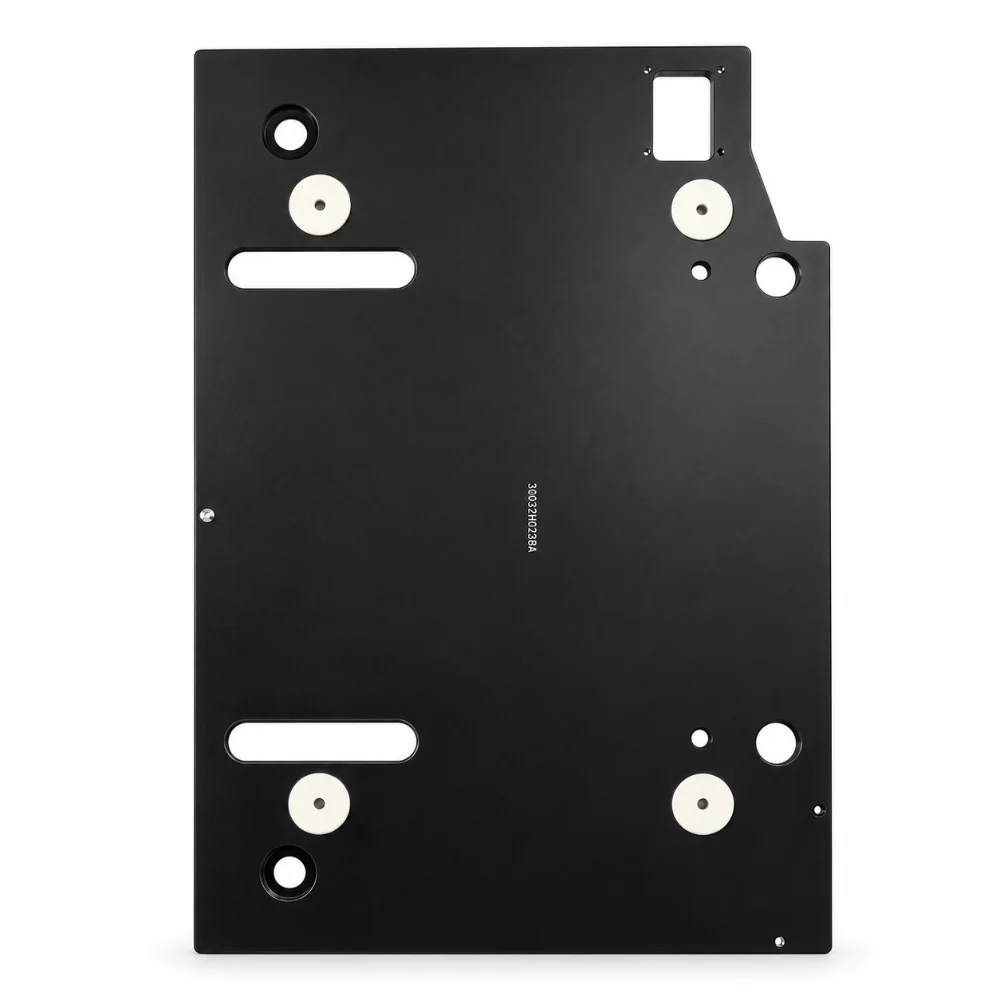
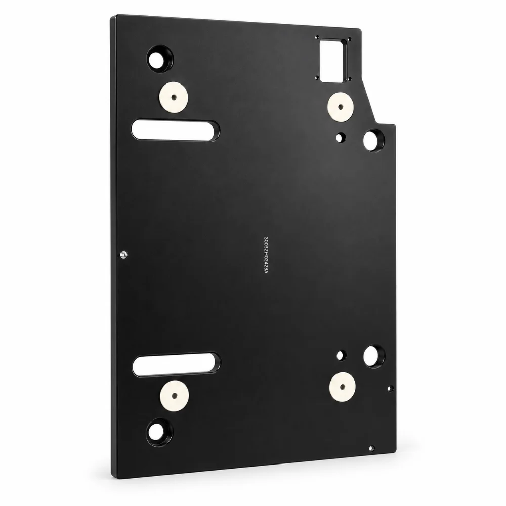
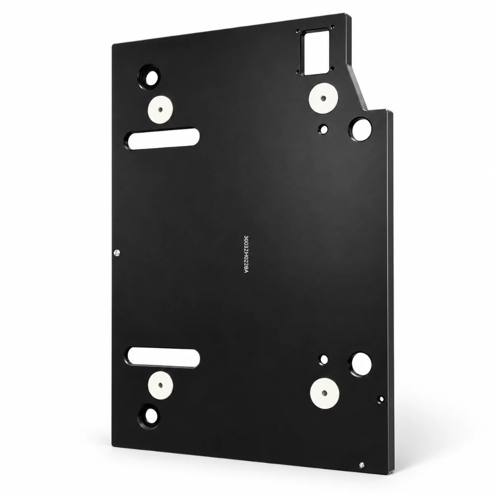


Aluminum Mounting Plate – CNC Machined Scanner Interface Base
This Aluminum Mounting Plate is a custom CNC machined component developed for a scanner mounting interface, where accurate hole positioning, dimensional stability, and consistent surface finishing are essential for proper assembly.
Manufactured from 6061-T6 aluminum, the plate features a large rectangular body, precision-machined mounting holes, elongated slots, a rectangular opening, and integrated support features. Black anodizing provides a uniform protective finish, while selected mechanical interfaces accommodate press-fit support components.
-
Product Name: CNC Machined Aluminum Scanner Mounting Plate
-
Material: 6061-T6 Aluminum Alloy
-
Manufacturing Process: CNC Milling, Drilling, Counterboring, and Threading
-
Surface Finish: Black Anodized, Type II, Class 2
-
Precision Requirement: ±0.001″ for designated dimensions
-
Main Features: Mounting Holes, Counterbores, Elongated Slots, Rectangular Opening, and Press-Fit Supports
-
Production Type: Custom Precision CNC Machining and Component Assembly
-
Application: Scanner Mount Interface / Equipment Mounting Base
 Get Free Quote


The Engineering Challenge: Keeping Multiple Mounting Points Aligned
Unlike a compact CNC component, a large aluminum plate can be affected by clamping pressure, machining stresses, and repositioning during production.
The important question is not simply whether each hole can be machined to size. It is whether the mounting features remain correctly positioned relative to one another across the entire part.
The drawing includes several distinct interface requirements.
Widely Spaced Hole Locations
The mounting holes are distributed around the plate rather than grouped in a single machining area. Their relative positions are important when the finished component is installed against a larger equipment frame.
A suitable machining strategy uses a consistent datum system and controlled workholding to minimize positioning differences between machining operations.
Elongated Slots for Assembly Adjustment
Two prominent elongated slots are visible on the plate, with additional openings serving separate mounting or clearance requirements.
These slots provide clearance or potential adjustment during assembly, depending on the mating component design.
Their rounded ends, slot widths, and positional relationships require particular attention during CNC milling.
Localized Mounting and Support Features
The design also includes a rectangular opening near one corner and multiple precision mounting features.
These localized details create different machining requirements within the same plate. The manufacturing plan must accommodate both large-profile machining and smaller, more precise operations without introducing unnecessary handling or alignment errors.
CNC Machining Strategy for a Large Aluminum Base Plate
The manufacturing approach for this type of part is primarily determined by feature relationships rather than geometric complexity alone.
1. Establishing Stable Machining Datums
Before machining the detailed features, the plate requires suitable reference surfaces and secure support.
Consistent datums help maintain the positional relationship between mounting holes, slots, and the overall machined profile.
2. Machining the Main Profile and Openings
CNC milling produces the outer geometry, elongated slots, and rectangular opening. Toolpath planning should account for the relatively large plate area and local transitions around its stepped corner.
3. Drilling and Counterboring
The engineering drawing identifies multiple hole groups with different diameter, depth, and positional requirements.
Through-holes and counterbores must be machined according to their individual specifications, particularly where a mounting fastener or mating component requires a defined seating surface.
4. Producing Threaded Interfaces
The design also contains metric threaded holes. Thread quality and alignment are important because these interfaces may be used for fastening or component positioning.
5. Preparing for Surface Finishing
After machining, the plate requires appropriate deburring and surface preparation. The drawing specifies that relevant threaded and precision-fit areas must be protected or treated according to the finishing requirements.
This prevents the decorative and protective coating from interfering with critical assembly interfaces.
Detailed Technical Specifications
| Parameter | Technical Specification |
|---|---|
| Product Name | Aluminum Mounting Plate / Scanner Mount Interface |
| Base Material | Aluminum 6061-T6 |
| Manufacturing Method | CNC Milling, Drilling, Counterboring and Tapping |
| Overall Dimensions | According to approved engineering model and drawing |
| Drawing Reference Length | 687.6 mm (reference dimension) |
| Drawing Reference Height | 420 mm |
| Selected Section Dimensions | 6.5 ±0.10 mm / 9.525 ±0.100 mm |
| Precision Tolerance | ±0.001″ (approximately ±0.025 mm) for designated features |
| Main Mounting Holes | 4 × Ø6.8 ±0.05 mm Through-Holes |
| Associated Counterbores | Ø11.5 ±0.2 mm |
| Additional Through-Holes | 2 × Ø13.0 mm, drawing-controlled tolerance |
| Metric Threaded Features | 2 × M6 × 1 and 4 × M3 × 0.5 Through-Threads |
| Surface Roughness | Ra 3.2 μm as specified in the project summary |
| Surface Treatment | Black Anodizing, MIL-A-8625F Type II, Class 2 |
| Marking | Laser-Etched Identification |
| Support Components | Press-Fit Support Buttons, No Adhesive |
| Inspection | Dimensional, Positional, Surface and Assembly Checks |
| Case Category | Precision CNC Machined Parts |
Note: Drawing-specific dimensional and geometric tolerances take precedence over general precision values. Overall dimensions should be confirmed against the final approved CAD revision.
Why Black Anodizing Requires Additional Planning
For this component, black anodizing is more than an appearance requirement.
The plate includes both exposed surfaces and functional interfaces. While the black finish provides a consistent appearance and improves surface corrosion resistance, anodizing also forms an oxide layer that can affect precision holes, threads, and mating surfaces.
The manufacturing drawing specifies Type II, Class 2 black anodizing and includes instructions for protecting selected areas during finishing.
This makes the order of operations important. Threaded or precision-fit features may require masking, controlled finishing, or post-finish machining, depending on their individual requirements.
The finished photographs show a dark anodized surface, contrasting metallic support features, and a clearly defined pattern of machined openings.
Press-Fit Assembly Without Adhesive
One notable feature of this mounting plate is the use of press-fit support components.
The engineering drawing specifies a press-fit assembly without glue, meaning the relevant support parts rely on their dimensional relationship with the receiving features.
For this type of assembly, several factors deserve attention:
- Receiving-hole dimensions must remain compatible with the press-fit component.
- The mounting surface must be protected against damage during installation.
- The assembled support features should maintain their intended positions relative to the plate.
- The insertion process should avoid excessive force that could damage the aluminum plate or its surface treatment.
Unlike a conventional mounting hole, a press-fit feature involves an additional assembly requirement that must be considered during both machining and inspection.
Inspection Priorities for Large-Format Mounting Plates
The inspection strategy for this component should focus on how individual machined features interact when the plate is assembled.
Overall Geometry and Flatness
A large plate requires control of its overall profile and reference surfaces. Inspection should establish whether the part remains suitable for installation after machining and anodizing.
Hole Position and Alignment
Critical mounting holes should be inspected relative to the specified drawing datums. Individual diameter checks alone are not sufficient to establish positional accuracy.
Counterbore and Slot Geometry
Counterbore depths, opening dimensions, and elongated slot profiles require checks to verify clearance and fit.
Thread Integrity
Threaded holes should be inspected using appropriate gauges, with attention to the requirements of the final finished condition.
Anodized Surface and Press-Fit Interfaces
The completed assembly should be checked for visible coating defects, burrs, scratches, and improper positioning of press-fit support components.
These controls are particularly important when the same plate design must be reproduced for equipment assembly.
Application in Equipment Mounting Systems
The drawing identifies the component as a Scanner Mount Interface Plate.
Its combination of a relatively large flat mounting area, precision hole groups, and localized fastening features is consistent with a purpose-built equipment interface.
Similar custom aluminum mounting plates may be designed for industrial scanning systems, automated inspection equipment, optical equipment supports, and specialized machinery.
The exact functional requirements depend on the surrounding equipment and mating components.
What This Case Demonstrates
This project illustrates the manufacturing considerations involved in producing a large aluminum mounting component with multiple precision interfaces.
Rather than relying on a single machining operation, this type of part requires coordination between CNC milling, precision hole production, anodizing preparation, and mechanical assembly.
For equipment manufacturers, these considerations are important when developing custom mounting plates that must integrate accurately with larger mechanical systems.
At Karry Precision, custom aluminum components can be evaluated for CNC machining based on approved drawings, material requirements, dimensional tolerances, surface finishes, and assembly specifications.
Frequently Asked Questions
1. What is an aluminum mounting plate used for?
An aluminum mounting plate provides a structural or positional interface between components in a mechanical assembly. This particular design is intended for a scanner mounting interface.
2. Why is 6061-T6 aluminum suitable for mounting plates?
6061-T6 aluminum offers a useful balance of mechanical strength, machinability, and corrosion resistance. It is also suitable for anodizing and is widely used in custom equipment components.
3. Can large aluminum plates be CNC machined with precision hole patterns?
Yes. CNC milling can produce large custom plates with precision holes, slots, and machined profiles. Achievable tolerances depend on plate geometry, thickness, fixturing, equipment capability, and the specified datums.
4. Does black anodizing affect mounting hole dimensions?
Anodizing forms an oxide layer on the aluminum surface. Where hole dimensions or mechanical fits are critical, coating thickness and masking requirements should be considered in the manufacturing plan.
5. Can mounting plates include press-fit components?
Yes. Press-fit inserts or support components can be incorporated into custom mounting plate designs when the receiving features and assembly requirements are properly specified.




