
 Contact Us
 Home / /
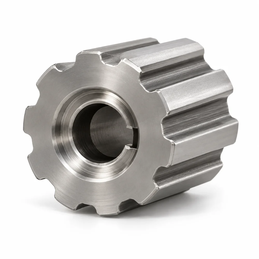
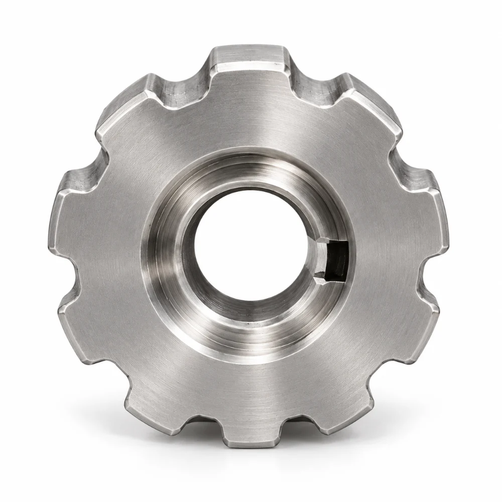
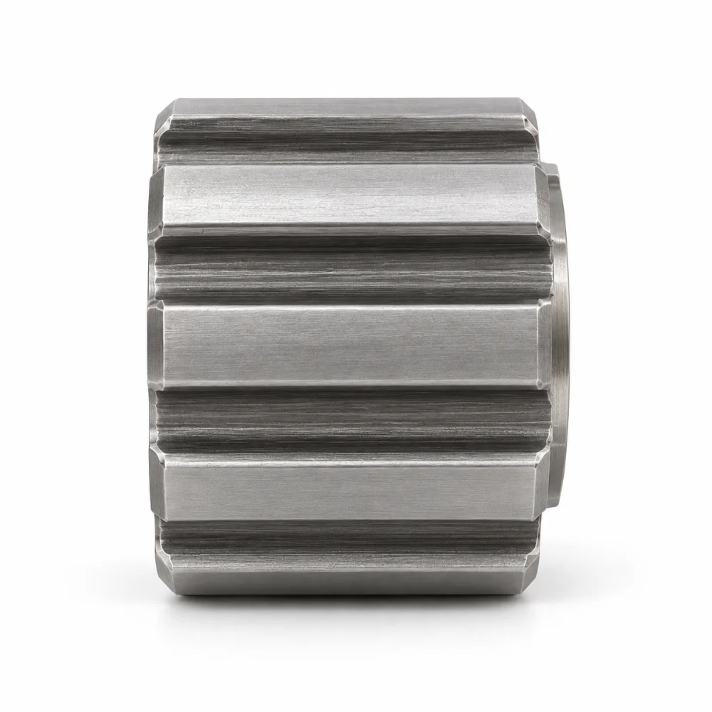


Custom Splined Hub with 10-Tooth Profile and Keyed Bore
This Splined Hub is a custom precision-machined steel component manufactured from 4140PH steel according to customer-supplied engineering drawings. It features a cylindrical body, ten external teeth, a central through-bore, and an internal keyway for connection to a mating shaft.
The component has an overall dimensional envelope of 29.62 × 29.12 × 25.5 mm, with a specified machining tolerance of ±0.001″ (approximately ±0.03 mm). Its design combines a profiled outer circumference with a keyed internal bore, making tooth geometry, bore alignment, and dimensional consistency important manufacturing considerations.
-
Product Name: Custom Splined Hub / 10-Tooth Keyed Pulley
-
Material: 4140PH Steel
-
Manufacturing Process: Precision CNC Turning and Profile Machining
-
Overall Dimensions: 29.62 × 29.12 × 25.5 mm
-
External Profile: 10 Teeth
-
Drawing-Specified Belt Pitch: 9.52 mm
-
Internal Features: Central Through-Bore and Keyway
-
Precision Tolerance: ±0.001″ (±0.03 mm), production requirement
-
Surface Roughness: Ra 1.6 μm
-
Surface Treatment: Standard
-
Inspection: Standard Inspection Report
-
Production Type: Custom Drawing-Based CNC Machining
 Get Free Quote


Ten External Teeth and One Central Connection
The most recognizable feature of this component is its external toothed profile.
Unlike a conventional smooth cylindrical hub, the outer surface is divided into ten repeating teeth extending along the axial length.
The original engineering drawing identifies the geometry as a toothed-belt pulley with a 9.52 mm pitch. Although the component has a spline-like external appearance, this distinction matters when evaluating the actual tooth form.
A timing-belt pulley and a standard involute spline do not necessarily share the same profile or inspection requirements.
For this project, the drawing-defined ten-tooth geometry is the correct manufacturing reference.
The central bore provides the second important interface. An internal keyway allows the hub to engage with a corresponding keyed shaft, provided the mating shaft and key dimensions follow the approved assembly design.
These two interfaces make the component more than a simple turned cylinder.
The Relationship Between Tooth Form and Shaft Alignment
For a toothed pulley, individual tooth dimensions matter, but their relationship to the rotational center is equally important.
If the outer profile is not correctly positioned relative to the central bore, the finished component may exhibit unwanted runout during rotation.
This is why the machining plan should consider the bore and external geometry as related features rather than independent operations.
External Tooth Geometry
The engineering drawing specifies a ten-tooth arrangement.
The machining process must reproduce the required tooth spacing and profile around the circumference.
Potential manufacturing considerations include tooth-to-tooth consistency, root transitions, edge condition, and the relationship between the tooth profile and the bore axis.
The appropriate cutting method should be selected according to the complete approved drawing, rather than assuming that a standard gear-cutting tool will automatically produce the correct belt-tooth geometry.
Internal Bore and Keyway
The central bore includes a visible keyway.
Unlike the outer teeth, which are defined by the belt engagement profile, this internal feature is associated with the shaft connection.
A suitable manufacturing plan should verify:
- Central bore diameter and geometry
- Keyway width and depth
- Keyway position relative to the bore
- Burr-free transitions at the bore opening
- Alignment between the bore axis and outer profile
The precise fit and key dimensions must follow the customer drawing and mating shaft requirements.
Why 4140PH Steel Changes the Machining Approach
The production specification identifies 4140PH steel as the material.
4140 is a chromium-molybdenum alloy steel used in mechanical components requiring a combination of strength and toughness. The PH designation indicates a prehardened material condition in the supplied production description.
Compared with more easily machined materials such as aluminum or free-machining brass, harder steel conditions can require additional attention to tool selection, cutting forces, and tool wear.
This becomes particularly relevant when creating multiple external tooth features.
Tool condition can affect the consistency of tooth surfaces and the transition between tooth flanks and roots.
For similar components, a practical process may use CNC turning for the cylindrical features followed by a suitable profile-cutting operation.
The exact production sequence depends on the specified tooth geometry and the available equipment.
Karry Precision provides CNC turning services for custom shaft-related and cylindrical components.
Where Turning Ends and Profile Machining Begins
The part contains two different types of geometry: rotational features and non-circular features.
The cylindrical surfaces and central bore are suitable candidates for CNC turning.
The external ten-tooth form requires a process capable of generating the specified tooth profile. Depending on the design, this may involve form milling or another suitable profile-generating method.
The internal keyway requires its own compatible machining operation.
This combination creates a machining sequence in which the reference geometry must remain consistent between setups.
| Feature | Machining Consideration |
|---|---|
| Cylindrical Body | Turning and dimensional control |
| Central Bore | Bore diameter and axis alignment |
| Ten External Teeth | Tooth profile and circumferential spacing |
| Internal Keyway | Keyway geometry and location |
| End Faces | Axial dimensions and edge condition |
| Surface Finish | Drawing-defined roughness requirement |
For a compact component, protecting finished surfaces during secondary operations is especially important.
Inspection Starts at the Mating Interfaces
The production summary specifies a precision tolerance of ±0.001″ (approximately ±0.03 mm) and a surface roughness requirement of Ra 1.6 μm.
These requirements should be interpreted together with the individual dimensional and geometric tolerances on the approved drawing.
A suitable inspection plan would focus on three groups of features.
First: The Rotational Geometry
The cylindrical dimensions, bore geometry, and relevant axis relationships should be measured against their specified limits.
Where the drawing requires concentricity or runout control, those requirements should be verified with an appropriate measuring setup.
Second: The External Tooth Profile
The ten-tooth profile should be checked for the required form and spacing. Visual inspection alone cannot establish tooth-profile accuracy.
The inspection method should follow the specified tooth standard and applicable dimensional requirements.
Third: The Keyway Interface
The bore and keyway should be checked for dimensional suitability.
Because the keyway participates in the mechanical connection, its finished edges and fit-related dimensions deserve particular attention.
The supplied production paperwork calls for a standard inspection report but does not include final measurement data. Therefore, this case describes the specified manufacturing and inspection requirements rather than claiming independently verified test results.
What the Finished Component Demonstrates
This project illustrates how a compact steel part can involve several different manufacturing considerations.
The external teeth define one mechanical interface. The central bore and keyway define another. Both must remain correctly related to the component's rotational axis.
The main technical value of this case is not the number of machining operations, but the need to coordinate those features within a small workpiece.
It also highlights why component identification matters. A toothed-belt pulley may resemble a splined hub, but the drawing's specific tooth profile governs how the part should be manufactured and evaluated.
Karry Precision supports custom CNC machining projects based on customer-supplied drawings, material requirements, and inspection specifications.
Frequently Asked Questions
What is a splined hub?
A splined hub generally uses a toothed connection to engage a mating shaft or component and transmit torque. Splines may be internal or external, depending on the design.
This particular component has an externally toothed pulley profile and an internal keyed bore, as identified by the engineering drawing.
Is a splined hub the same as a timing pulley?
No. A splined hub typically engages a corresponding splined mechanical component, while a timing pulley uses a specifically designed tooth profile to engage a toothed belt.
The two may have similar appearances but different geometry and functions.
Why is 4140PH steel used for machined mechanical components?
4140PH steel provides strength and toughness suitable for many mechanical applications. Its machining requirements depend on the supplied material condition, hardness, and component geometry.
Can CNC machining produce an external ten-tooth profile?
Yes. External tooth profiles can be manufactured using suitable CNC and gear-profile machining methods. The selected process depends on tooth shape, pitch, required accuracy, and production volume.
Why is the keyway important in this component?
The keyway provides a defined connection feature for a mating keyed shaft. Correct bore and keyway dimensions are important for achieving the intended assembly fit.
What should buyers provide when ordering custom toothed hubs?
Buyers should provide a 2D engineering drawing, 3D model, material specification, tooth profile or standard, bore and keyway dimensions, required tolerances, quantity, and any inspection or finishing requirements.




