
 Contact Us
 Home / /


PTFE Parts: CNC Machined Flanged Housing with M4 Inserts
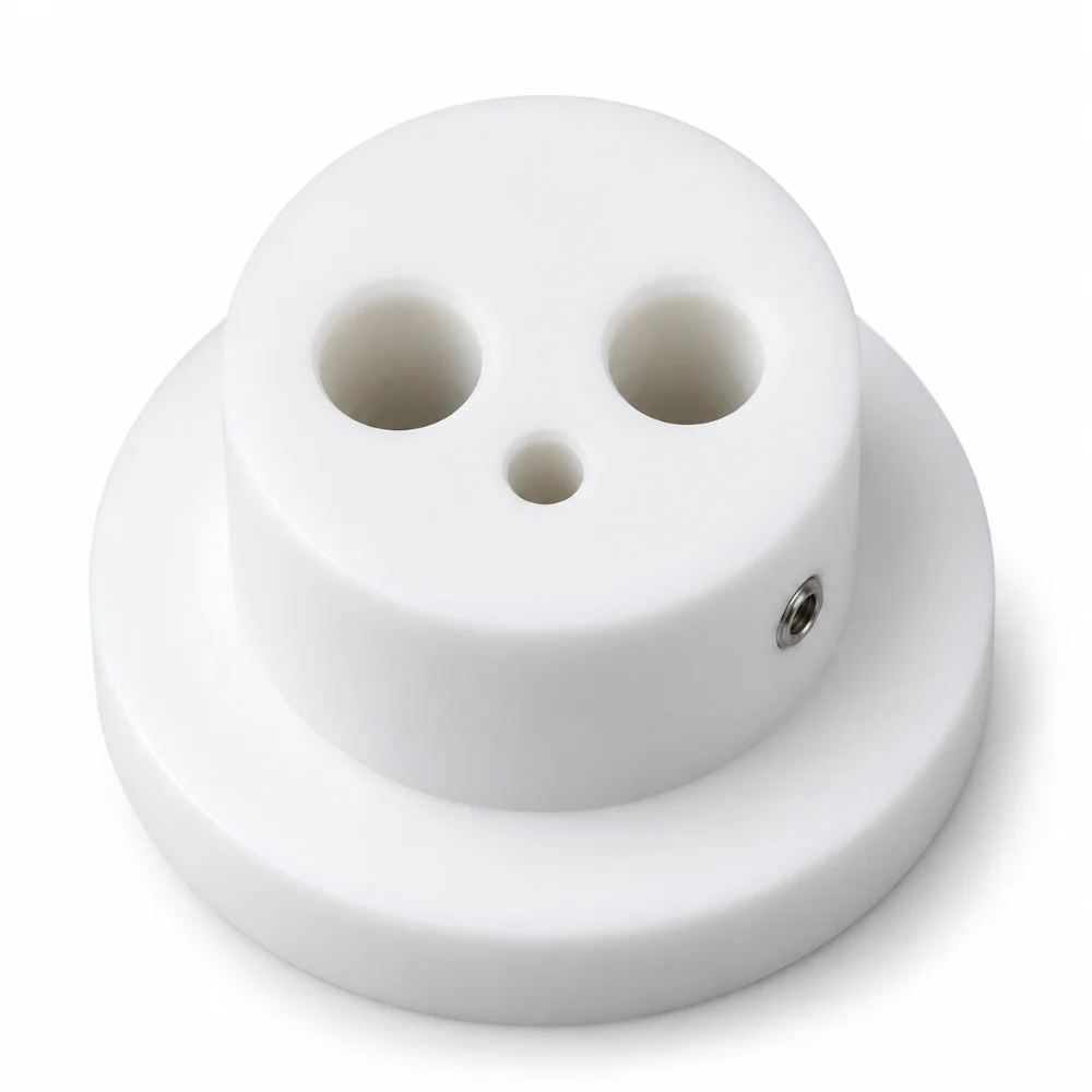
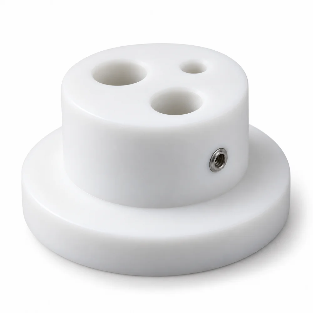
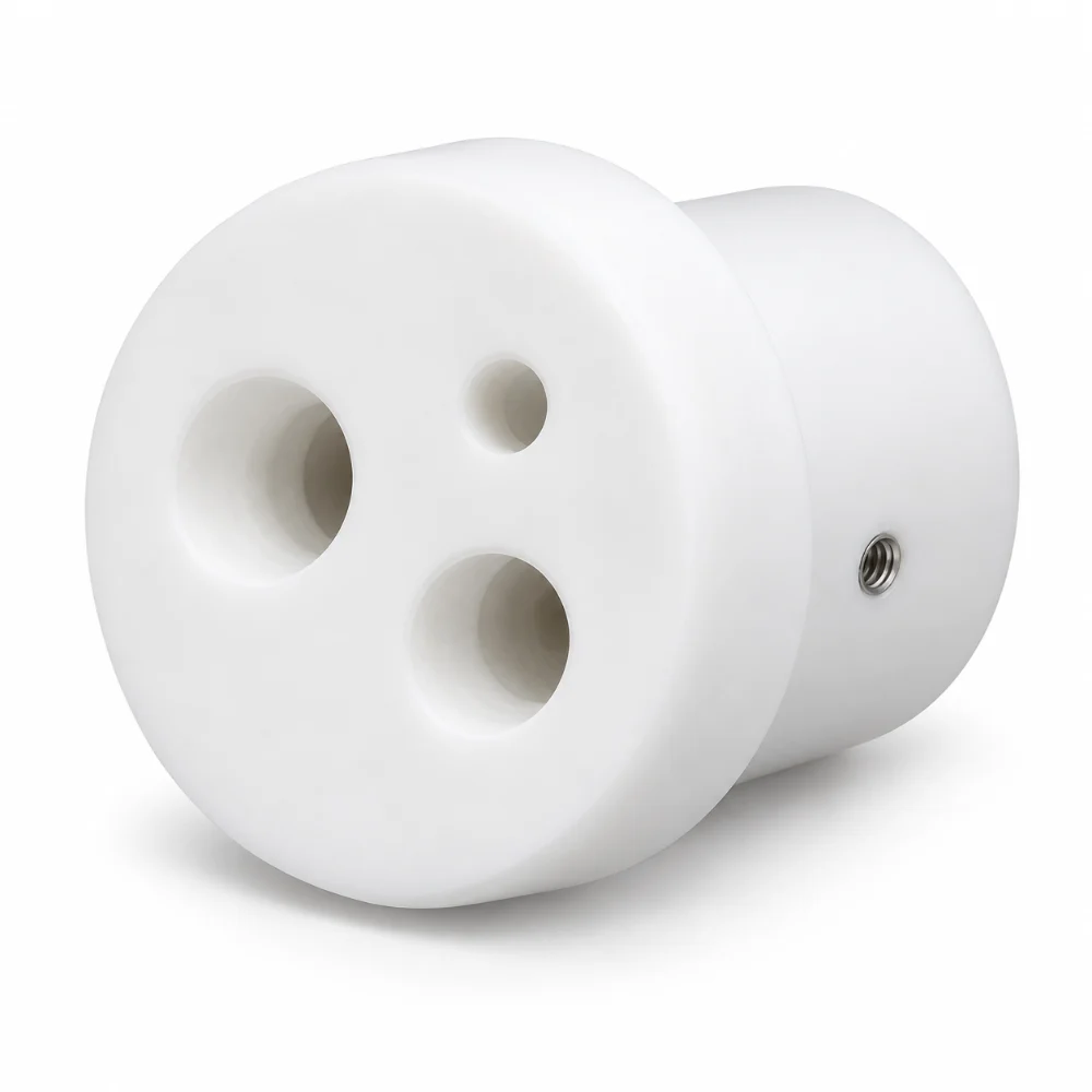
A precision-machined part made from white polytetrafluoroethylene (PTFE) with a dense texture that is precision-machined to customer provided engineering drawings. The part consists of circular mounting flange with raised cylindrical body and 3 axial through holes and specified metal threaded inserts.
The overall size is 100 × 100 × 80 mm, base flange Ø100 mm, upper section Ø62 mm. The general dimensional tolerance is shown as±0.010″ (or 0.25 mm). With this project, the machining factors for manufacturing soft engineering plastic components with multiple holes and reinforced threaded joints are emphasized.
-
Product Name: Custom CNC Machined PTFE Housing
-
Material: White PTFE / Polytetrafluoroethylene
-
Suggested Manufacturing Process: CNC Turning, Drilling and Secondary Hole Machining
-
Overall Dimensions: 100 × 100 × 80 mm
-
Base Flange: Ø100 × 20 mm
-
Upper Body: Ø62 × 60 mm
-
Through-Holes: 2 × Ø14 mm and 1 × Ø8 mm
-
Threaded Features: 2 × M4 Side Connections
-
Thread Inserts: 2 × Helisert M4 × 9 (Drawing Requirement)
-
General Tolerance: ±0.010″ (±0.25 mm)
-
Surface Roughness: Ra 6.3 μm on the engineering drawing; Ra 3.2 μm in the production notes
-
Surface Treatment: None Specified
-
Production Basis: Customer Engineering Drawing
 Get Free Quote


Why This PTFE Part Is More Than a Simple Turned Cylinder
The two-diameter external profile is relatively straightforward compared with many metal components. However, the combination of a soft plastic body, closely arranged axial holes, and transverse threaded connections changes how the part should be approached.
The upper cylindrical section is considerably narrower than the base flange. This creates a shoulder that must remain consistent with the drawing while the material is held securely during machining.
The real manufacturing considerations lie in the internal features. Two Ø14 mm holes run through the component, a smaller Ø8 mm hole is offset from the center, and the side connections are specified to communicate with the larger bores.
These interacting features require more attention than the outside shape alone suggests.
Holding PTFE Without Distorting the Flange
PTFE has different machining behavior from aluminum, brass, or stainless steel.
Its relatively low stiffness means that excessive clamping pressure can temporarily deform the workpiece. A component may appear dimensionally correct while restrained but change slightly after the clamping force is released.
For a part with a Ø100 mm flange and Ø62 mm upper body, a suitable turning setup should distribute holding pressure and support the workpiece without damaging finished surfaces.
Possible machining considerations include:
- Using suitable support during external diameter turning
- Avoiding unnecessary clamping pressure
- Controlling cutting forces and localized heat
- Allowing the component to relax before final inspection
- Checking the relationship between the flange and upper cylindrical body
The exact fixture and cutting sequence depend on the available raw material and manufacturing equipment.
Karry Precision provides CNC turning services for custom plastic and metal components.
Three Axial Holes, Each with a Different Machining Role
The top face contains three visible holes, but they do not share the same size or position.
Two Ø14 mm through-holes are positioned on opposite sides of the central axis. The drawing locates their centers 15 mm to either side of the centerline.
The smaller Ø8 mm through-hole is positioned along the perpendicular centerline, offset from the circular center.
This arrangement is important because the component also contains transverse threaded connections.
Drilling the Ø14 mm Through-Holes
Deep-hole machining in PTFE requires suitable chip evacuation, cutting geometry, and workpiece support.
PTFE chips can behave differently from those of brittle metals, and excessive tool pressure may affect the hole geometry.
For this component, the two Ø14 mm through-holes must remain correctly positioned relative to the circular external profile.
Producing the Offset Ø8 mm Hole
The smaller Ø8 mm hole adds another feature to the top face.
Its offset position means that the machining program must reference the correct centerlines rather than assuming that all holes are concentric.
The hole diameter and position should be verified according to the approved engineering drawing.
Metal Threaded Inserts in a Soft Plastic Body
One of the most distinctive aspects of this project is the specified use of M4 threaded inserts.
The drawing calls for two transverse M4 features communicating with the Ø14 mm holes, together with Helisert M4 × 9 inserts.
For PTFE components, reinforced threads may be considered when an assembly requires repeated fastening or more dependable thread engagement than an unsupported plastic thread can provide.
However, insert performance depends on installation geometry, support, loading, and the material's tendency to deform under sustained stress.
The Insert Installation Consideration
The machining and assembly plan should address the relationship between the threaded insert and its prepared hole.
Important points include maintaining the specified insertion location, avoiding excessive installation force, and preventing damage to the surrounding PTFE.
The finished thread also needs to remain accessible for its intended mating component.
The drawing establishes the insert specification, but it does not provide tightening torque, pull-out strength, or installation test results. Those requirements would need separate verification.
Surface Roughness: Resolving Two Different Requirements
This case contains a useful example of why engineering drawings and production instructions must be checked together.
The original drawing specifies machined surfaces at Ra 6.3 μm, while the accompanying production summary lists Ra 3.2 μm.
| Source | Surface Roughness Requirement |
|---|---|
| Engineering Drawing | MRR Ra 6.3 μm |
| Production Summary | Ra 3.2 μm |
| Final Acceptance | Confirm the controlling specification before inspection |
Ra 3.2 μm represents a finer finish than Ra 6.3 μm, but the two values should not be treated as interchangeable.
Before final machining and inspection, the customer-approved requirement should be clarified.
PTFE surface finish is also influenced by cutting tool sharpness, feed conditions, and the material's response to the cutting action.
Unlike anodized aluminum or plated metal, this component has no specified additional surface coating.
Inspection Priorities for the Finished PTFE Housing
The general tolerance is ±0.25 mm, but individual features and threaded insert requirements must be assessed separately.
| Feature | Inspection Priority |
|---|---|
| Ø100 mm Base Flange | External diameter and flange geometry |
| 20 mm Flange Thickness | Dimensional verification |
| Ø62 mm Upper Body | Diameter and concentric relationship |
| 80 mm Overall Height | Finished axial dimension |
| 2 × Ø14 mm Holes | Diameter, position and through-hole condition |
| Ø8 mm Hole | Diameter and offset position |
| M4 Insert Features | Position, thread accessibility and installation condition |
| Machined Surfaces | Applicable surface roughness requirement |
PTFE components should be measured using methods that avoid excessive contact pressure.
Where dimensional changes caused by temperature are relevant, the inspection conditions should also be controlled.
The supplied documentation requests a standard inspection report, but actual measurement results have not been provided.
What This Project Shows About Custom PTFE Machining
This component illustrates a specific manufacturing challenge: producing a relatively simple cylindrical shape while maintaining the accuracy of several interacting internal features.
The external flange can be approached as a turning operation, while the axial holes and transverse connections introduce additional machining requirements.
The specified metal inserts also create a material interface that is absent from conventional one-piece machined plastic components.
This makes the case particularly relevant to buyers sourcing custom plastic housings, flanged components, and mechanical parts with reinforced threads.
The end-use function has not been independently established from the available documentation, so no pressure rating, sealing performance, or operating load is claimed.
Frequently Asked Questions
Can PTFE parts be CNC machined?
Yes. PTFE can be machined using CNC turning, milling, drilling, and other suitable processes. Tool selection, workholding, and cutting parameters should account for its relatively soft and flexible behavior.
Why are metal threaded inserts used in PTFE parts?
Metal threaded inserts can provide a reinforced fastening interface. Their suitability depends on installation geometry, loading conditions, and the creep characteristics of the surrounding PTFE.
What is the difference between machining PTFE and aluminum?
PTFE is less rigid and more susceptible to deformation under clamping loads. Its thermal expansion and cutting behavior also differ from aluminum, making workpiece support and inspection conditions important.
Can PTFE housings have multiple through-holes?
Yes. CNC machining can produce multiple holes of different diameters and positions. The machining process must account for hole depth, spacing, tool access, and the surrounding wall thickness.
What tolerances are specified for this PTFE component?
The project documentation specifies a general tolerance of ±0.010″ (±0.25 mm). Individual features may require additional drawing-specific checks.
Can Karry Precision manufacture custom PTFE parts from drawings?
Karry Precision offers custom CNC machining services for engineering plastics, including PTFE. Customers can submit 2D drawings and 3D CAD models for a review of material specifications, machining feasibility, tolerances, and order requirements.




