
 Contact Us
 Home / /
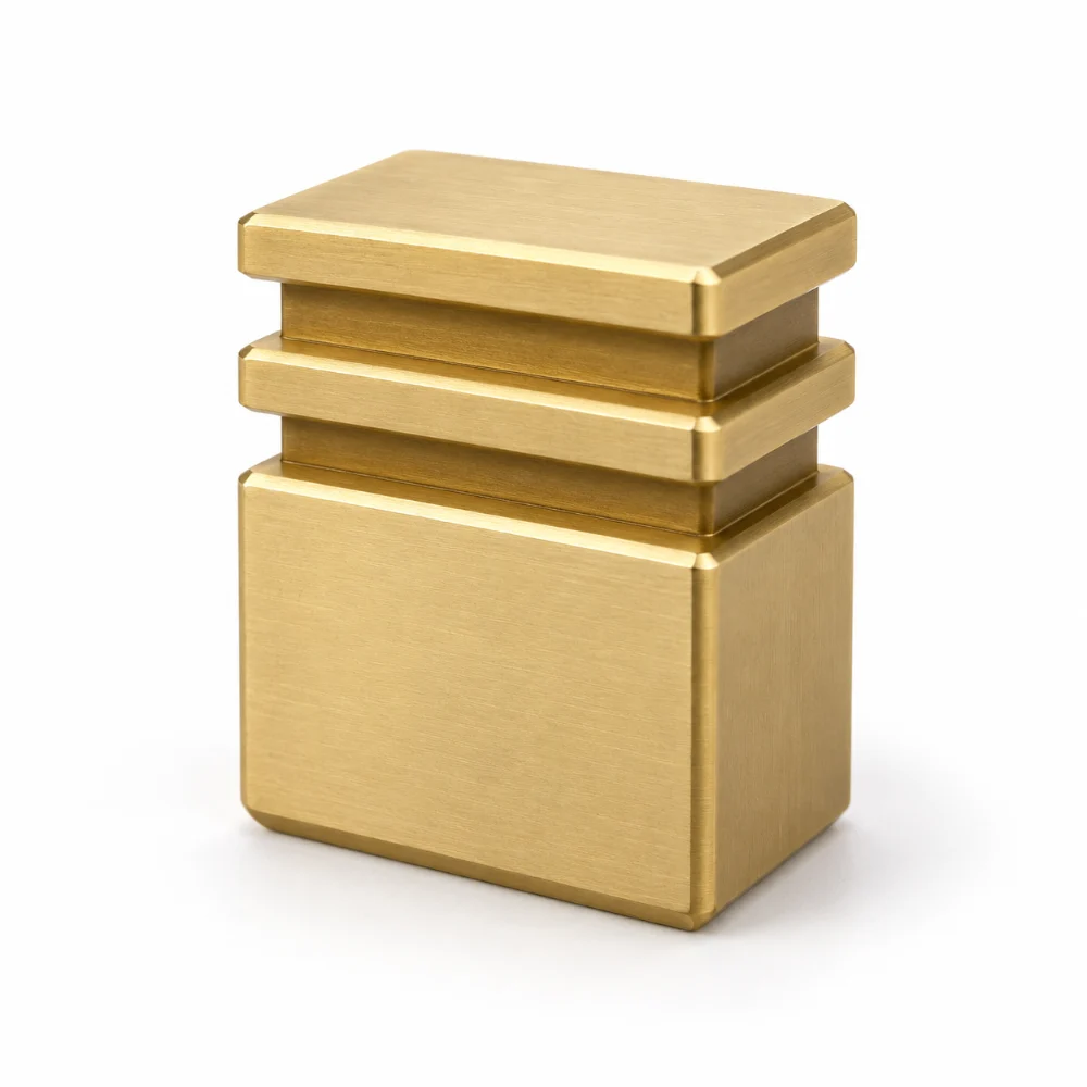



CNC Machined Brass Block with Precision Stepped Grooves
The CNC Machined Brass Block is a precision component made of C360 brass with custom precision machining based on clients' engineering drawings. It has a small, rectangular body and recessed grooves with raised sections, along with well-defined chamfered sides.
The component measures 20 × 15 × 12 mm and has a specified general tolerance of ±0.005″ (±0.13 mm). Requirements in its engineering are Ra surface roughness of 1.6 μm and dimensional control and surface quality are both important factor during manufacturing.
-
Product Name: Custom CNC Machined Brass Block
-
Material: C360 Free-Machining Brass
-
Overall Dimensions: 20 × 15 × 12 mm
-
Suggested Manufacturing Process: Precision CNC Milling
-
Dimensional Tolerance: ±0.005″ (±0.13 mm)
-
Surface Roughness Requirement: Ra 1.6 μm
-
Main Features: Rectangular Base, Two Recessed Grooves, Three Raised Lands
-
Edge Features: 0.30 × 45° Typical Chamfers / 1.00 × 45° Chamfer
-
Threaded Holes: None
-
Surface Treatment: Standard, No Additional Coating Confirmed
-
Inspection: Standard Dimensional Inspection Report
-
Manufacturing Type: Custom Drawing-Based CNC Machining
 Get Free Quote


The Detail That Makes This Brass Block Different
At first glance, the component appears to be a simple rectangular brass block. A closer look reveals that the upper section is divided into three raised lands by two narrow recessed grooves.
The lower portion retains a broader rectangular profile, while the top features a narrower, stepped arrangement.
This difference between the base and upper geometry is the main manufacturing consideration.
The part is not a conventional drilled mounting block. The supplied documentation lists no threaded holes, and the photographed component is defined primarily by its external shape.
The challenge is therefore concentrated on machining the shoulders and grooves consistently without compromising the surrounding surfaces.
How the Two-Groove Profile Influences CNC Milling
Establishing the Rectangular Base
The drawing specifies a nominal overall envelope of 20 × 15 × 12 mm.
Before machining the detailed upper features, the rectangular base must provide suitable reference surfaces for subsequent operations.
For this type of component, a practical machining plan would establish flat faces and the required external dimensions before the finer grooves are finished.
The base geometry should be checked against the specified overall dimensions and any additional requirements contained in the 3D model.
Creating the Narrower Upper Profile
The drawing identifies a 13 mm dimension across the upper stepped section, compared with the 15 mm dimension of the broader body.
This creates a visible change in width between different portions of the component.
Machining these transitions requires controlled cutter positioning and appropriate finishing allowances.
The shoulders should be formed without leaving unwanted burrs or tool marks at the intersections between adjacent surfaces.
Milling Two Parallel Recesses
The two recessed grooves separate the upper section into three visible raised lands.
Unlike a broad pocket, narrow recesses require attention to cutter accessibility, groove width, and the finished condition of the groove walls.
A suitable machining strategy should address:
- Consistent spacing between raised sections
- Straight and well-defined groove boundaries
- Suitable tool clearance inside the recesses
- Minimal burr formation along the groove edges
- Protection of the adjacent finished faces
The supplied drawing includes 2 mm nominal step-related dimensions. Exact unlisted groove geometry should be taken from the accompanying 3D model.
Explore Karry Precision's CNC milling capabilities for custom grooved profiles and small brass components.
Machining C360 Brass Without Damaging Fine Edges
C360 is a free-machining brass grade commonly used for precision components.
Its machinability makes it suitable for producing small external features, stepped profiles, and detailed milled surfaces.
However, good machinability does not eliminate the need for suitable tooling and workholding.
The relatively small size of this component means that the cutting tool, fixture, and finished edges must be considered together.
A cutter that performs well on a broad surface may not be appropriate for a narrow groove.
Likewise, excessive clamping pressure may leave marks on the brass surface.
For similar workpieces, selecting appropriate cutting conditions and protecting finished faces during repositioning can help preserve the intended geometry.
Chamfers Are Part of the Design
The engineering drawing includes 0.30 × 45° typical chamfers and a separate 1.00 × 45° chamfer callout.
These features should not be treated simply as cosmetic edge finishing.
Their location and size form part of the specified component geometry.
Chamfer machining should therefore follow the drawing rather than relying on general manual deburring.
Surface Finish: Why Ra 1.6 μm Matters
The production documentation specifies a surface roughness requirement of Ra 1.6 μm (63 μin) for the part.
This requirement is especially relevant because the component contains multiple small faces, grooves, and shoulders.
Different features may require different cutting approaches to achieve the specified surface quality.
For example, finishing a broad external face is not the same as finishing a narrow recessed surface.
Tool wear, feed rate, cutting stability, and burr removal can all affect the final appearance.
The finished component should be evaluated against the applicable surface roughness and inspection requirements.
No additional plated or anodized coating is confirmed in the supplied production documentation.
Drawing Requirements and Inspection Priorities
This project provides a useful example of how a compact part can contain several different inspection requirements despite having no threaded holes.
| Drawing Feature | Specification | Inspection Focus |
|---|---|---|
| Overall Envelope | 20 × 15 × 12 mm | Basic dimensional verification |
| Upper Stepped Width | 13 mm nominal | Upper profile geometry |
| Two Recessed Grooves | Per 2D drawing and 3D model | Groove location and shape |
| General Tolerance | ±0.005″ / ±0.13 mm | Applicable dimensional limits |
| Surface Roughness | Ra 1.6 μm | Finished surface texture |
| Typical Chamfer | 0.30 × 45° | Edge geometry |
| Additional Chamfer | 1.00 × 45° | Specified chamfer feature |
| Threaded Features | None | Confirm absence of unintended holes |
A standard inspection plan for comparable components may include dimensional measurements using calipers or micrometers, optical checks of small stepped features, and appropriate surface roughness measurement.
The photographs show finished parts, while the supplied production document specifies standard inspection reporting. Actual measurement results have not been provided, so individual compliance results are not claimed here.
Karry Precision's tolerance and quality control information explains its broader inspection capabilities.
From a 2D Drawing to a Small Custom Brass Component
The drawing provides the primary external dimensions, groove-related callouts, and chamfer requirements.
It also instructs the manufacturer to refer to the 3D model for dimensions not shown on the drawing.
That detail is important for this project.
The shape may look simple in a photograph, but the complete geometry of its narrow recesses and step transitions cannot be determined from appearance alone.
For a drawing-based CNC milling order, the final CAD model should be reviewed together with the 2D specifications before selecting tools, preparing the machining program, and establishing inspection points.
The supplied manufacturing information identifies this as a custom C360 brass component but does not establish its final assembly function. The case therefore concentrates on the machining requirements rather than assigning an unverified end-use application.
Frequently Asked Questions
What is a CNC machined brass block?
A CNC machined brass block is a custom brass component produced by removing material with computer-controlled cutting tools. It may contain stepped profiles, slots, grooves, mounting features, or other drawing-specific geometry.
Is C360 brass suitable for precision CNC milling?
Yes. C360 is widely used for precision machining because of its good machinability. It is suitable for many small mechanical components and detailed external profiles.
Can CNC milling produce two narrow grooves in a small brass part?
Yes. Narrow grooves can be machined using suitable milling tools and cutting strategies. The required cutter and process depend on groove width, depth, geometry, and available tool access.
What surface roughness is specified for this brass block?
The supplied production specification calls for Ra 1.6 μm (63 μin). This is a manufacturing requirement, not a reported measured result.
Does this component require threaded holes or plating?
The production notes list no threaded holes. The surface treatment is described as standard, and no additional coating has been confirmed.




