
 Contact Us
 Home / /
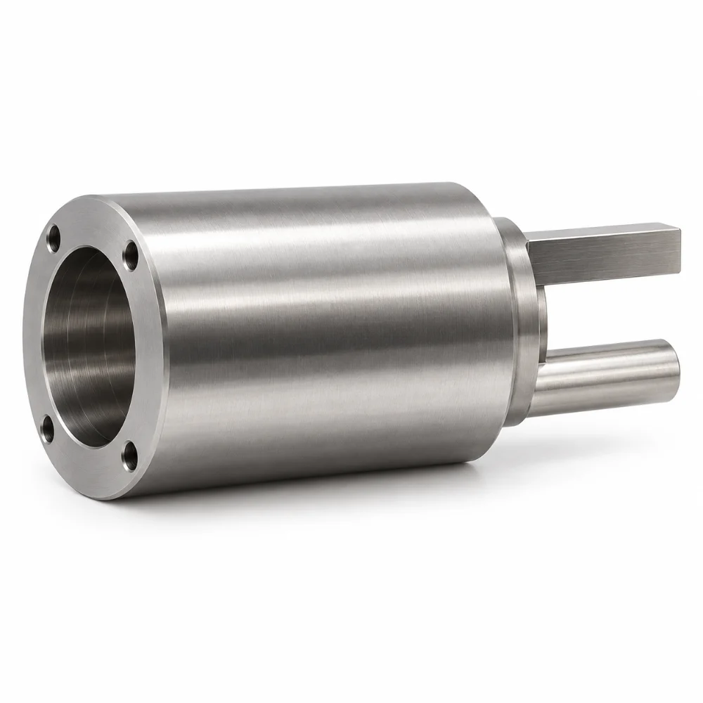
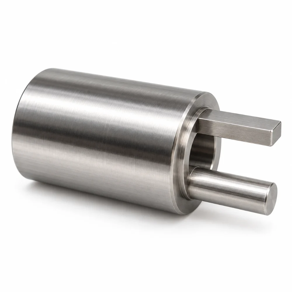


Precision Steel Sleeve with Stepped Bore and Slotted Drive End
This Precision Steel Sleeve is a custom-machined cylindrical component designed for mechanical assemblies requiring accurate bore alignment, reliable mounting, and a specialized engagement interface.
Manufactured from A2 tool steel, the component combines a cylindrical outer body, stepped internal bores, four threaded mounting holes, and a slotted end geometry. The drawing specifies controlled machining tolerances, through hardening to 48–52 HRC, and Titanium Nitride surface treatment.
-
Product Name: Precision Steel Sleeve
-
Material: A2 Tool Steel
-
Overall Dimensions: 47.1 × 23.81 × 23.81 mm
-
Machining Process: CNC Turning, Boring, Milling, Drilling and Tapping
-
Critical Tolerance: ±0.001" (Approximately ±0.03 mm)
-
Hardness Requirement: 48–52 HRC
-
Surface Finish Requirement: Ra 3.2 μm
-
Specified Coating: Titanium Nitride (TiN)
-
Main Features: Stepped Bore, Four Threaded Mounting Holes, Slotted Drive End
-
Production Type: Custom Precision Machined Component
 Get Free Quote


A Sleeve Designed Around Two Different Interfaces
The most interesting feature of this component is the difference between its two ends.
One end has a circular opening surrounded by four threaded mounting holes. The opposite end incorporates a slotted geometry with projecting features, rather than a conventional flat-ended cylindrical profile.
The internal bore is also stepped, creating different internal diameters along the sleeve axis.
These details mean that the component cannot be treated as a simple turned tube. Its outside diameter, internal bore, threaded-hole pattern, and slotted end must maintain the dimensional relationships defined in the engineering drawing.
For manufacturing, the challenge is therefore not just producing a smooth cylindrical surface. It is maintaining the required alignment between features created through different machining operations.
Where the Manufacturing Complexity Comes From
1. Maintaining a Common Axis Across Stepped Internal Bores
The sleeve includes a main internal bore specified at Ø15.04 mm and a smaller Ø12.25 mm feature toward the opposite end.
The transition between these diameters creates an internal shoulder. This geometry introduces an additional consideration during boring because the cutting process must control both diameter and axial position.
CNC turning and boring operations should reference a consistent centerline wherever practical. This helps control concentricity between the internal features and outer cylindrical surface.
Particular attention is required at the internal transition, where tool clearance, chip evacuation, and machining stability may influence the finished geometry.
2. Four Small Threaded Holes Around the Mounting Face
The circular mounting face includes four threaded holes positioned around the main opening.
The drawing specifies Ø1.60 mm drilled holes with a depth of 5.20 mm, followed by M2 × 0.4–6H internal threading to a depth of 4 mm.
These holes are relatively small compared with the body diameter, making accurate positioning and thread quality important.
The machining plan must account for drill alignment, controlled tapping, and removal of burrs around the hole entrances.
Inspection should verify both thread engagement and hole location relative to the sleeve axis.
3. Machining the Slotted End Without Losing Alignment
The opposite end introduces a different type of machining requirement.
Its slotted profile creates separated projecting sections that are geometrically distinct from the cylindrical body. The drawing also includes angular requirements associated with this end geometry.
Because these features interact with the central axis and internal bore, their orientation matters as much as their individual dimensions.
A suitable milling setup should maintain a stable datum relationship during material removal. Cutting parameters and workholding must also account for the interrupted geometry and local changes in stiffness.
This is the feature that most clearly separates the Precision Steel Sleeve from a standard cylindrical spacer or bushing.
Machining A2 Tool Steel Before and After Hardening
A2 tool steel is selected for applications requiring a combination of wear resistance, hardness, and dimensional stability.
However, the drawing's 48–52 HRC requirement introduces another manufacturing consideration: the relationship between machining and heat treatment.
A suitable production strategy must consider how much material to remove before hardening and whether critical dimensions require additional finishing afterward.
Thermal processing can introduce dimensional variation. For a component with a controlled internal bore and several interconnected features, this possibility must be considered when planning machining allowances.
The drawing also specifies a Titanium Nitride surface treatment. Coating requirements should be reviewed alongside dimensional limits, particularly where material build-up could affect fitting surfaces, bores, or threaded features.
The finishing sequence should therefore be determined by the final dimensional and surface specifications rather than by appearance alone.
Detailed Technical Specifications
| Parameter | Specification |
|---|---|
| Product Name | Precision Steel Sleeve |
| Material | A2 Tool Steel |
| Overall Dimensions | 47.1 × 23.81 × 23.81 mm |
| Main Outer Diameter | Ø23.81 mm |
| Mounting Hole Pitch Circle | Ø19.05 mm |
| Main Internal Bore | Ø15.04 mm |
| Smaller Internal Bore Feature | Ø12.25 mm |
| Mounting Hole Quantity | 4 |
| Mounting Hole Drilling | Ø1.60 mm × 5.20 mm Deep |
| Internal Thread | M2 × 0.4–6H × 4 mm Deep |
| Precision Requirement | ±0.001" (±0.03 mm) for Designated Features |
| Hardness | 48–52 HRC |
| Heat Treatment | Through Hardening |
| Surface Roughness | Ra 3.2 μm / 125 μin |
| Specified Surface Treatment | Titanium Nitride (TiN) |
| Machining Method | CNC Turning, Boring, Milling, Drilling and Tapping |
| Inspection | Dimensional, Bore, Thread and Feature Alignment Checks |
Note: Individual tolerances and finishing requirements are governed by the approved engineering drawing. The values above describe specified requirements rather than independently verified measurement results.
Inspection Priorities for the Finished Sleeve
For this component, final inspection needs to establish more than whether the overall length and diameter are within tolerance.
Internal bore dimensions: The stepped bores should be checked independently. Their dimensions and relative alignment influence how the sleeve interfaces with associated components.
Mounting face geometry: The four-hole pattern must be checked for positional accuracy and thread quality. Hole spacing alone does not establish correct alignment with the central bore.
Slotted-end profile: The projecting features require inspection of their geometry, orientation, and edge condition. Small differences in this region may influence engagement with a mating component.
Hardness and finishing: The specified hardness range should be verified after heat treatment. Any required coating should also be assessed against the applicable finishing and dimensional requirements.
Together, these checks help ensure that the sleeve meets its intended mechanical interface requirements rather than simply its external appearance.
Potential Mechanical Applications
A precision sleeve with this combination of cylindrical locating surfaces, internal bores, threaded mounting points, and a specialized engagement end may be suitable for several types of equipment.
Potential applications include:
- Precision Mechanical Assemblies: Components requiring controlled coaxial positioning and accurately machined mounting interfaces.
- Industrial Automation Equipment: Custom sleeves integrated into positioning or mechanical engagement assemblies.
- Specialized Drive Interfaces: Applications where a slotted end connects with a corresponding mechanical feature.
- Custom Machine Components: Drawing-specific parts requiring hardened tool steel and multiple precision-machined features.
The exact operating application depends on the complete mating assembly and its design requirements.
What Makes This Precision Steel Sleeve Different?
The manufacturing value of this project lies in the combination of features rather than any single machining operation.
A conventional sleeve may require only turning, boring, and basic dimensional inspection.
This design adds four small internal threads, a stepped bore, an angularly defined slotted end, through-hardening requirements, and a specified surface treatment.
Each operation affects the next.
A properly planned machining sequence and drawing-based inspection approach are essential for maintaining the necessary relationships between these features.
For similar custom parts, Karry Precision can evaluate machining feasibility, material requirements, dimensional specifications, and suitable manufacturing processes before production.
Frequently Asked Questions
1. What material is specified for this Precision Steel Sleeve?
The engineering drawing specifies A2 tool steel. The material is suitable for components requiring good wear resistance and the ability to undergo through hardening.
2. Why does this sleeve have two different internal bore diameters?
The stepped bore provides two distinct internal geometries within the same component. Their exact functions depend on the mating assembly, but maintaining their dimensions and alignment is an important machining consideration.
3. What is the required hardness for this component?
The specified hardness is 48–52 HRC after through hardening. Actual hardness should be verified against the applicable heat-treatment and inspection requirements.
4. Why is the slotted end more difficult to machine than a regular cylindrical end?
The slotted end introduces interrupted geometry and orientation requirements that cannot be completed through conventional turning alone. Additional milling and feature inspection are needed.
5. Can similar precision sleeves be manufactured with different dimensions or materials?
Yes. Custom sleeve designs can be evaluated for alternative diameters, lengths, internal bore arrangements, threaded-hole patterns, and material grades according to the intended application.




