
 Contact Us
 Home / /
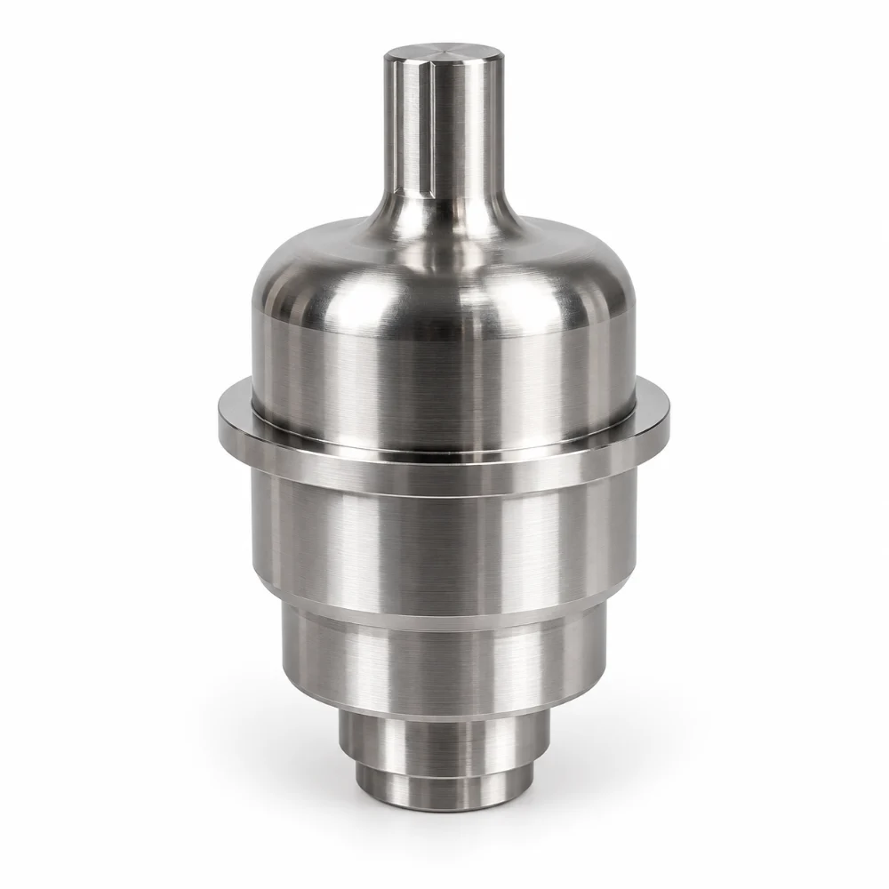
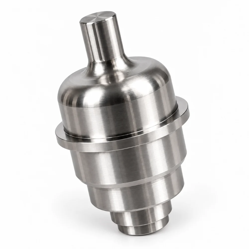
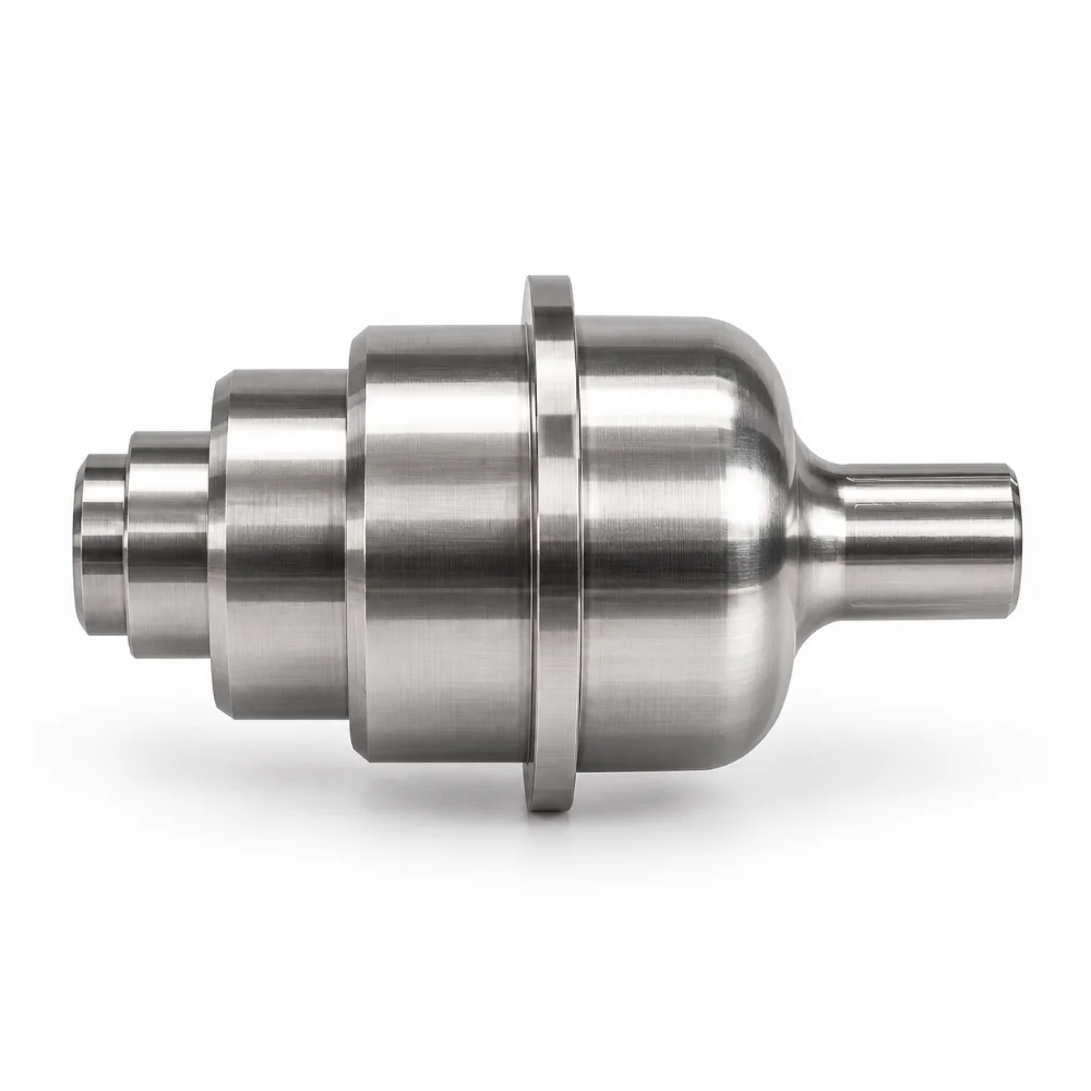


Precision Machined Shaft in 4340 Steel with Tight Diameter Control
This Precision Machined Shaft is a custom CNC turned component manufactured from 4340 alloy steel for precision mechanical assembly applications. Its design incorporates multiple stepped diameters, defined shoulder positions, a locating flange, and a smaller end section that requires accurate machining relative to the main rotational axis.
With an overall length of 131.00 mm and a maximum diameter of 80.00 mm, the component is primarily produced through CNC turning. Particular attention is required for the closely toleranced Ø70.000 mm section, critical axial dimensions, geometric alignment, and specified surface finish.
-
Product Name: Precision Machined Shaft / Stepped Steel Shaft
-
Material: 4340 Alloy Steel
-
Manufacturing Process: Precision CNC Turning
-
Overall Dimensions: 131.00 × 80.00 × 80.00 mm
-
Main Features: Stepped Cylindrical Profiles, Flange, Shoulders and End Features
-
Precision Requirement: ±0.001″ (Approx. ±0.03 mm) for Designated Features
-
Specified Surface Finish: Ra 0.4 μm (16 μin)
-
Manufacturing Type: Custom CNC Turned Component
 Get Free Quote


The Most Important Dimension Is Not the Largest One
Although the shaft has a maximum outer diameter of 80 mm, the most demanding dimensional requirement is associated with a smaller cylindrical section.
The engineering drawing defines a nominal Ø70.000 mm diameter with positive deviations of +0.043 mm and +0.056 mm. This creates a permitted diameter range of 70.043–70.056 mm.
For machining purposes, this is fundamentally different from applying a conventional symmetrical tolerance around 70 mm.
The cutting program, tool compensation, and inspection procedure must all account for the specified positive tolerance zone.
A shaft may appear dimensionally correct when measured against its nominal size, yet still fall outside the allowable limits for an intended fit.
This makes diameter control one of the defining technical requirements of the project.
Multiple Shoulders, One Rotational Reference
The component contains several cylindrical sections separated by shoulders and diameter transitions.
Rather than treating these steps as independent features, the machining process must preserve their positional relationship along the shaft axis.
Two important drawing dimensions are:
- 94.30 ±0.05 mm: A specified axial distance associated with the stepped profile.
- 67.30 ±0.05 mm: Another controlled axial dimension defining part of the shaft geometry.
The drawing also identifies diameters of Ø60.00 mm, Ø33.00 mm, Ø28.50 mm, and a smaller Ø22.23 ±0.05 mm end section.
Each dimension contributes to the overall arrangement of the shaft.
In particular, small variations in shoulder position can influence how mating components are located axially, even when individual diameters remain within tolerance.
For this reason, an effective turning strategy should maintain stable axial references throughout the machining sequence.
CNC Turning Strategy for a Stepped 4340 Steel Shaft
4340 alloy steel is commonly selected for mechanical components requiring a combination of strength and toughness. Its machinability depends on the material condition, cutting parameters, and tooling.
For this shaft geometry, CNC turning provides a practical method for producing the main cylindrical surfaces and stepped shoulders.
Roughing the Main Cylindrical Profile
The initial turning operation establishes the basic external profile while leaving appropriate stock for finishing.
Because the shaft includes several diameter changes, roughing should avoid excessive loading near narrow sections and shoulder transitions.
The cutting sequence must also consider workpiece support and the relationship between the largest cylindrical section and the smaller end features.
Finishing the Critical Diameter
The Ø70.000 mm section requires controlled finishing passes and suitable dimensional verification.
Tool wear, temperature, workpiece deflection, and cutting conditions can all influence the finished diameter.
Instead of relying only on the nominal programmed dimension, the finishing operation should be adjusted to achieve the drawing's actual upper and lower limits.
Controlling the Shoulder Faces
The shaft contains multiple axial reference surfaces, including a projecting flange and shoulders between cylindrical sections.
Where practical, related diameters and shoulder faces can be finished within a consistent setup to reduce errors introduced by repositioning.
Any additional setup should preserve the established reference axis and protect previously finished surfaces.
Completing End Features
The drawing includes smaller end geometry and a specified 4.80 mm slot-related feature.
Such details may require additional machining depending on the tooling configuration and approved manufacturing plan.
Their dimensions and angular relationships should be checked independently from the main turned surfaces.
Detailed Technical Specifications
| Parameter | Specification |
|---|---|
| Product Name | Precision Machined Shaft |
| Drawing Description | Shaft V3 Short |
| Material | 4340 Alloy Steel |
| Preferred Manufacturing Process | CNC Turning (Lathe) |
| Overall Length | 131.00 mm |
| Maximum Outer Diameter | Ø80.00 mm |
| Critical Fit Diameter | Ø70.000 mm, +0.043 / +0.056 mm |
| Additional Diameters | Ø60.00 / Ø33.00 / Ø28.50 mm |
| End Section Diameter | Ø22.23 ±0.05 mm |
| Specified Axial Dimension 1 | 94.30 ±0.05 mm |
| Specified Axial Dimension 2 | 67.30 ±0.05 mm |
| Keyway / Slot Width Callout | 4.80 mm |
| Precision Tolerance Target | ±0.001″ (Approx. ±0.03 mm) |
| General Unmarked Tolerance | ±0.13 mm |
| Geometric Controls | Datum-Referenced Controls of 0.03 mm and 0.05 mm, Per Drawing |
| Specified Surface Roughness | Ra 0.4 μm / 16 μin at Designated Surface |
| Surface Treatment | Standard, No Additional Coating Specified |
| Inspection | Drawing-Based Dimensional and Geometric Inspection |
Note: Individual dimensional and geometric tolerance callouts take precedence over the general machining tolerance. Material heat-treatment condition and final hardness are not specified in the available drawing.
How Alignment and Surface Finish Affect the Finished Shaft
A precision shaft is not defined only by its overall length and external diameters.
The relationship between surfaces can be equally important, especially where a part contains a narrow locating feature, multiple shoulders, and a larger supporting diameter.
The engineering drawing includes geometric requirements referenced to Datums A and B, with control values of 0.03 mm and 0.05 mm for designated features.
These requirements establish relationships that cannot be verified by measuring individual diameters alone.
For inspection, the appropriate approach is to establish the specified datum references before checking the controlled features.
The drawing also identifies a fine surface roughness requirement of Ra 0.4 μm (16 μin) at a designated location.
Achieving this finish may require a carefully controlled finishing pass, appropriate tooling, and verification using a surface roughness instrument.
A visually smooth surface does not automatically demonstrate compliance with a specified Ra value.
Inspection Focus: Fit, Position and Surface Condition
The inspection priorities for this shaft are closely connected to its stepped geometry and dimensional requirements.
Critical diameter verification
The Ø70.000 mm feature should be measured against its asymmetric tolerance limits, rather than the nominal diameter alone.
Axial position verification
Specified shoulder locations and overall length should be checked against the drawing dimensions. The 94.30 mm and 67.30 mm dimensions require particular attention because of their ±0.05 mm tolerance callouts.
Geometric relationship inspection
Where datum-referenced controls apply, inspection must evaluate the relationship between the designated surfaces using suitable measuring equipment and methods.
Surface finish measurement
The Ra 0.4 μm requirement should be verified at the indicated surface, not assumed to apply to every external feature.
Transition and edge inspection
Shoulders, corner transitions, and smaller end features should be examined for burrs, machining marks, and edge defects that could interfere with assembly.
These checks form a practical inspection plan for drawing-controlled shaft production. Actual acceptance remains subject to the approved drawing and recorded measurement results.
Where Similar Precision Machined Shafts Are Used
The drawing identifies this component as a short shaft but does not establish a specific end-use machine.
Similar 4340 steel stepped shafts may be considered for several types of equipment, depending on loading conditions, fits, and assembly design.
Industrial Power Transmission
Stepped shafts can provide defined mounting diameters and shoulder locations for mating mechanical components.
Precision Machinery
Controlled diameter transitions and accurate axial dimensions are useful where a shaft must interface with bearings, spacers, or other rotating components.
Automation Equipment
Custom cylindrical components can serve as positioning or transmission elements within specialized mechanical assemblies.
Custom Equipment Development
Drawing-specific shafts allow designers to establish nonstandard lengths, stepped profiles, and fit dimensions that may not be available from standard catalog components.
The final application must be evaluated against the required mechanical loading, material condition, operating environment, and assembly specifications.
What This Machining Project Demonstrates
The manufacturing significance of this precision machined shaft lies in the relationship between its dimensions.
Its largest diameter is relatively straightforward to turn, but the narrow positive tolerance on the Ø70 mm section, the controlled shoulder positions, and the datum-referenced geometry require a coordinated machining approach.
The project demonstrates why producing a shaft to an engineering drawing involves more than machining an external cylindrical profile.
A successful manufacturing plan must consider which surfaces establish the reference geometry, which dimensions directly affect fit, and how those relationships will be verified.
At Karry Precision, our CNC turning services support custom alloy steel shafts, stepped cylindrical parts, and other precision mechanical components manufactured according to defined material, dimensional, and inspection requirements.
Frequently Asked Questions
1. What is a precision machined shaft?
A precision machined shaft is a cylindrical mechanical component manufactured with controlled dimensional and geometric requirements. Depending on its design, it may include stepped diameters, shoulders, grooves, mounting features, or other machined interfaces.
2. Why is 4340 steel used for precision shaft machining?
4340 is a nickel-chromium-molybdenum alloy steel valued for its potential strength and toughness. Its suitability for a particular shaft depends on material condition, heat treatment, loading requirements, and the intended operating environment.
3. Can CNC turning produce a shaft with an asymmetric diameter tolerance?
Yes. CNC turning can produce asymmetric tolerance zones when the machining process, workholding, tool compensation, and measurement strategy are appropriate. The finished dimension must comply with the specified upper and lower limits.
4. How are stepped shaft shoulders inspected?
Shoulder positions can be inspected using suitable dimensional measurement equipment and reference surfaces. Where geometric tolerance controls are specified, the appropriate datums must also be established during inspection.
5. Does every surface of a precision machined shaft require the same finish?
No. Surface roughness requirements may vary depending on the function of each feature. A drawing may specify a fine finish for particular contact or locating surfaces while allowing different finishes elsewhere.




