
 Contact Us
 Home / /
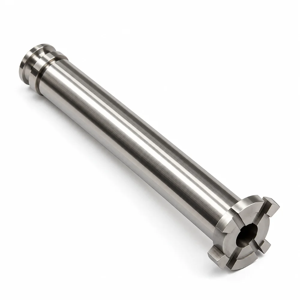
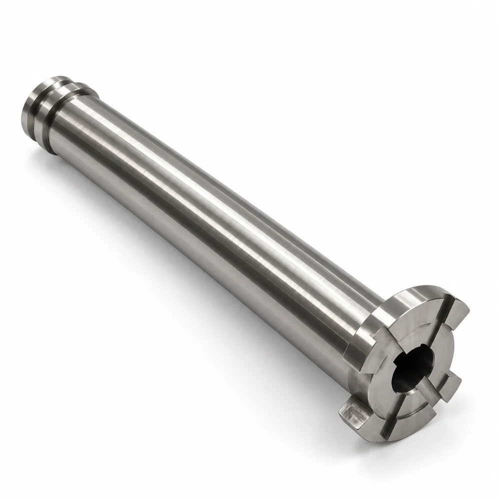
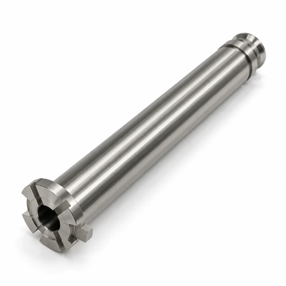


M6 Insert Head – Precision CNC Machining of A2 Tool Steel
This M6 Insert Head is a custom precision-machined tool component designed for use with M6 brass insert applications. Its elongated cylindrical body, specially machined engagement head, and internal bore geometry require accurate CNC machining to achieve the specified dimensions and functional features.
Manufactured from A2 tool steel, the component incorporates a stepped cylindrical profile, a central internal bore, and multiple radial slots at the working end. The engineering specification also calls for through hardening to 48–52 HRC and a titanium nitride surface treatment, making dimensional control and finishing sequence important considerations.
-
Product Name: M6 Insert Head / Brass M6 Insert Head
-
Material: A2 Tool Steel
-
Manufacturing Process: Precision CNC Turning, Drilling, Milling and Slotting
-
Overall Dimensions: 92.4 × 18.0 × 15.59 mm
-
Heat Treatment: Through Hardening
-
Specified Hardness: 48–52 HRC
-
Specified Surface Treatment: Titanium Nitride (TiN)
-
Surface Roughness: Ra 3.2 μm
-
Precision Requirement: ±0.001″ (approximately ±0.03 mm) on designated features
-
Part Number: 591350M001
-
Production Type: Custom Precision Machined Tool Component
 Get Free Quote


Why the M6 Insert Head Requires More Than Conventional Turning
The body of this component appears straightforward: a long cylindrical shaft with a larger feature at one end. However, the functional geometry becomes more complex when examining the internal bore and the segmented working face.
The drawing identifies an 18 mm head diameter and a sequence of internal diameters along the component axis. The working end also includes radial slots with angular relationships defined in the engineering drawing.
These features introduce three separate machining considerations: maintaining a consistent axis along the shaft, preserving the relationship between internal and external diameters, and machining the end-face details without damaging the surrounding edges.
For an insert installation tool, these details can influence how the head engages with its mating component. The final suitability must be established against the intended M6 insert geometry and assembly requirements.
Machining the Segmented Working End
The working end is the most visually distinctive feature of this M6 Insert Head.
Instead of a continuous circular face, the head incorporates several radial slots that divide portions of the outer engagement profile. The drawing specifies angular positions, including 120° relationships, together with narrow slot dimensions.
These features require a machining approach different from ordinary cylindrical turning.
After producing the primary turned profile, the end slots can be machined using controlled milling operations. The cutting sequence should account for the relatively small features and their proximity to the central opening.
Particular attention is required at the intersections between the slots, central bore, and outer head diameter. Excessive burr formation at these points could interfere with mating contact or subsequent finishing.
This combination of turned and milled geometry makes the component a useful example of precision CNC machining for specialized tooling.
Maintaining the Internal Bore and Shaft Relationship
The drawing shows a stepped internal passage extending along the component axis, including specified diameters of Ø6.00 mm, Ø7.75 mm, and Ø12.00 mm in their respective locations.
The internal geometry is not a single uniform hole. Its diameter changes along the length of the tool, making the sequence of drilling and subsequent internal machining important.
The principal manufacturing consideration is maintaining the relationship between the internal passage and the external cylindrical surfaces.
A suitable process begins with establishing the principal turning datum before machining the corresponding internal features. Depending on tool access and workholding, additional operations may be used to achieve the specified bore transitions.
The drawing also identifies a 25.00 mm axial dimension associated with the head-end internal geometry. This dimension must be interpreted together with the sectional view rather than treated as an independent overall bore depth.
For quality verification, the individual bore diameters and applicable axial dimensions should be inspected against their respective drawing callouts.
Heat Treatment and Surface Finishing Considerations
A2 tool steel was specified for this component rather than a softer general-purpose machining material.
The engineering requirements identify through hardening and a finished hardness range of 48–52 HRC. This hardness specification is especially relevant because the tool includes narrow slots, precision bores, and a long cylindrical section.
Heat treatment can introduce dimensional changes, depending on the material condition, section geometry, and processing cycle. Consequently, the machining allowance and finishing sequence should be reviewed before manufacturing.
Where final dimensional accuracy requires it, critical surfaces may need finishing operations after heat treatment.
The drawing also specifies titanium nitride (TiN) as the surface treatment. The coating process, required coating thickness, and any masking requirements should be confirmed before production because these factors may affect fitted dimensions.
The specified surface treatment should not be confused with the base material: the component itself is manufactured from A2 tool steel.
Detailed Technical Specifications
| Parameter | Technical Specification |
|---|---|
| Product Name | M6 Insert Head |
| Drawing Description | Brass M6 Insert Head |
| Part Number | 591350M001 |
| Base Material | A2 Tool Steel |
| Overall Size | 92.4 × 18.0 × 15.59 mm |
| Head Outside Diameter | Ø18.00 mm |
| Internal Bore Features | Ø6.00 / Ø7.75 / Ø12.00 mm, per drawing |
| Selected Axial Dimension | 25.00 mm, per sectional drawing |
| Working-End Geometry | Radial slots and segmented engagement profile |
| Angular Features | 30°, 60° and 120° references, as detailed on drawing |
| Manufacturing Method | CNC Turning, Drilling, Milling and Slotting |
| Heat Treatment | Through Hardening |
| Specified Hardness | 48–52 HRC |
| Surface Treatment Requirement | Titanium Nitride (TiN) |
| Surface Roughness | 125 μin / Ra 3.2 μm |
| Critical Dimensional Tolerance | ±0.001″ (approximately ±0.025 mm) |
| Inspection Reference | Approved Engineering Drawing |
| Manufacturing Category | Precision Turned and Machined Tooling Parts |
Note: Values are based on the supplied engineering drawing. Individual feature tolerances, including any unilateral limits, take precedence over the general precision requirement. Surface treatment is listed as a drawing specification rather than an independently verified coating result.
Inspection Focus: Three Features That Matter Most
For this type of tooling component, quality inspection should emphasize the features most likely to affect assembly and engagement, rather than relying only on the overall length.
1. Working-End Profile
The width, angular position, and edge condition of the radial slots should be checked against the specified geometry.
Visual inspection should also identify remaining burrs around the slot intersections and central opening.
2. Shaft and Internal Bore Geometry
The shaft diameter, internal bore diameters, and axial transitions require dimensional verification.
Appropriate measuring instruments should be selected according to the feature size, accessibility, and tolerance requirement.
3. Post-Heat-Treatment Condition
The specified 48–52 HRC hardness range should be verified using an appropriate hardness testing procedure.
Where required, critical dimensions should be inspected after heat treatment to confirm that the component remains within the applicable drawing tolerances.
The finished surface and coating requirements should be assessed separately in accordance with the approved finishing specification.
Where This Type of Insert Head Can Be Used
The drawing describes the component as a Brass M6 Insert Head. Its precise installation equipment and operating conditions are not identified.
Similar custom insert heads may be designed for the following applications:
Brass Threaded Insert Installation
Specialized heads used in equipment designed to position or install threaded brass inserts into compatible assemblies.
Assembly Tooling
Custom machined tool components that must engage a specific insert geometry during controlled assembly operations.
Industrial Production Equipment
Precision tooling elements used in dedicated installation stations or automated manufacturing systems.
Replacement Tooling Components
Drawing-specific machined heads intended to match an existing mechanical tooling interface.
The exact equipment compatibility depends on the engagement geometry, material requirements, and operating conditions.
What Makes This Project Different
The primary manufacturing challenge is not the size of the component but the number of functional features concentrated within a relatively compact working head.
The component combines a long turned shaft, stepped internal diameters, angularly positioned end slots, and a specified hardened material condition.
Each of these details affects manufacturing decisions differently. Turning establishes the main cylindrical geometry, drilling and internal machining create the bore features, milling produces the engagement slots, and heat-treatment planning addresses the specified hardness without overlooking dimensional stability.
This case illustrates how CNC turning and secondary precision machining can be combined to manufacture specialized A2 tool steel components with more complex functional geometry than a conventional cylindrical pin.
Frequently Asked Questions
1. What is an M6 Insert Head?
An M6 Insert Head is a specialized tooling component associated with M6 insert applications. Its exact geometry depends on the insert and installation mechanism. This particular design includes a cylindrical shaft, stepped internal bore, and segmented working end.
2. Is this insert head manufactured from brass?
No. Although the drawing identifies the part as a Brass M6 Insert Head, the specified manufacturing material is A2 tool steel. The name refers to its intended brass insert application rather than its base material.
3. Why is A2 tool steel suitable for precision tooling components?
A2 tool steel is commonly selected for tooling that requires hardenability, wear resistance, and dimensional stability when appropriately processed. Actual performance depends on the final hardness, geometry, and working conditions.
4. Can CNC machining produce the radial slots and stepped internal bores?
Yes. These features can be produced through a combination of CNC turning, drilling, internal machining, and precision milling. Suitable workholding and inspection are important for maintaining the required feature relationships.
5. Can the M6 Insert Head be customized for different insert designs?
Yes. Custom versions can be evaluated with changes to the shaft length, head diameter, internal bore geometry, engagement slots, material, or heat-treatment requirements. Manufacturing feasibility should be reviewed against the complete engineering drawing.




