
 Contact Us
 Home / /
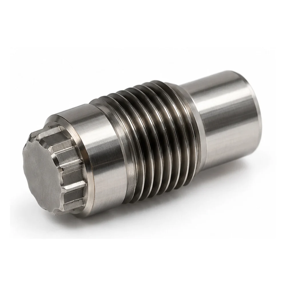


Nozzle Thread Chaser – Precision CNC Turned A2 Tool Steel Component
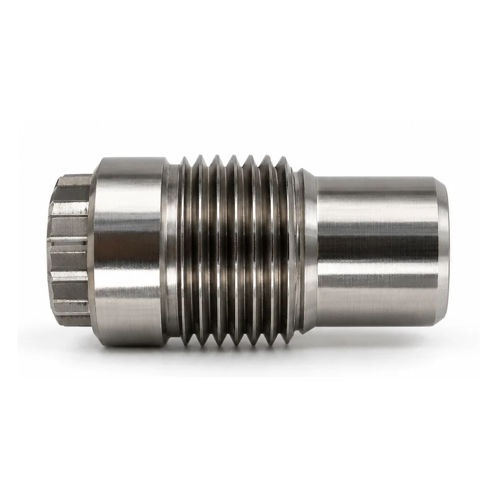
This Nozzle Thread Chaser is a compact precision-machined tool steel component featuring a stepped cylindrical profile, an external threaded section, and a 12-point socket interface. Its design combines several functional surfaces within a short overall length, making accurate thread machining and concentric feature alignment particularly important.
Manufactured from A2 tool steel, the component measures approximately 38.1 mm in overall length and incorporates a 7/8-14 UN-2A external thread. The design also specifies a Higbee blunt thread start, a lead-thread feature, and a 9/16-inch 12-point socket reference, requiring coordinated CNC turning and secondary machining operations.
-
Product Name: Nozzle Thread Chaser
-
Material: A2 Tool Steel
-
Alternative Material: S7 Tool Steel
-
Machining Process: Precision CNC Turning, External Threading and Socket Machining
-
Overall Size: 38.1 × 22.23 × 22.23 mm
-
External Thread: 7/8-14 UN-2A
-
Drive Interface: 9/16″ 12-Point Socket Reference
-
Special Thread Design: Higbee Blunt Start and Lead Thread
-
General Production Tolerance: ±0.005″ (±0.13 mm), subject to individual drawing callouts
-
Surface Roughness Requirement: 125 μin / Ra 3.2 μm
-
Production Type: Custom CNC Turned Tool Steel Component
 Get Free Quote


Why the Thread Start Deserves More Attention Than the Overall Shape
At first glance, this component resembles a conventional threaded cylindrical fitting. Its stepped body and external thread are relatively straightforward to recognize.
The more demanding feature lies at the beginning of the thread.
The engineering design specifies a Higbee blunt thread start, which differs from the sharp, incomplete leading thread often found on standard machined fasteners.
A Higbee-style thread start removes or modifies the incomplete thread crest at the entry point, helping create a more controlled initial engagement with a compatible mating thread.
This detail matters because the first contact between threaded components can influence how easily they start engaging.
For the nozzle tooling design, the thread entrance is therefore a functional machining feature rather than merely a visual finishing detail.
The drawing additionally identifies a lead-thread requirement, making the entry geometry one of the most important areas to control during production.
A Compact Component with Three Different Interfaces
The overall design can be understood through three distinct sections.
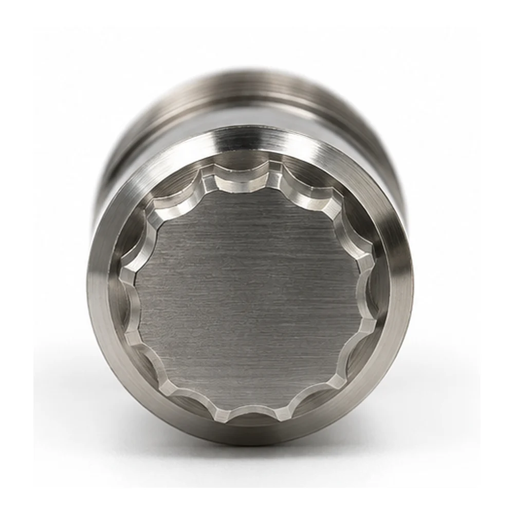
The 12-Point Socket End
One end incorporates a 12-point socket profile with a nominal 9/16-inch reference.
Unlike an ordinary hexagonal interface, the multi-point profile requires careful control of its internal shape and dimensional relationship to the surrounding cylindrical body.
The machining strategy must account for the socket profile, corner geometry, and suitable tool engagement.
The External Threaded Body
The central portion contains the specified 7/8-14 UN-2A external thread.
Its nominal diameter is 7/8 inch, with 14 threads per inch.
The thread is bounded by stepped shoulders and transition features, so the machining process must consider not only the thread itself but also the adjacent relief areas.
The Smooth Cylindrical End
The opposite end features a reduced-diameter cylindrical section with a chamfered transition.
Its geometry provides an additional locating or mating surface, depending on the final equipment configuration.
The relationship between the threaded section and smooth cylindrical end makes concentricity and consistent turning references important considerations.
Together, these three interfaces give the component a distinct structure that is considerably different from a long-shaft thread chasing tool.
What Makes Machining the Higbee Thread Start Different?
Producing a standard external thread generally involves controlling thread pitch, diameter, depth, and profile.
A blunt-start thread adds another consideration: the geometry of the first usable thread.
The thread-start modification must be compatible with the specified thread form without introducing unwanted deformation or burrs at the entrance.
For this design, a practical manufacturing approach involves generating the main thread geometry and then applying the required thread-start finishing operation.
The process must preserve the 7/8-14 UN-2A thread specification while achieving the intended entry profile.
Careful inspection is particularly important around the transition between the blunt start and the first complete thread.
If this area is excessively rounded, incompletely machined, or damaged during finishing, it may affect mating engagement.
For these reasons, the Higbee entry geometry should be evaluated separately from a general visual inspection of the thread.
Coordinating CNC Turning with Socket Profile Machining
The component is predominantly rotational, which makes CNC turning a suitable primary manufacturing process.
Turning operations can establish the main cylindrical diameters, stepped shoulders, relief features, and external thread preparation.
The challenge changes at the socket end.
The 12-point interface is not a simple turned feature. Depending on equipment and tooling selection, it may require a dedicated broaching, shaping, or other profile-machining operation.
The critical objective is to maintain alignment between this socket and the turned component axis.
Suitable workholding also becomes important because the component is relatively short.
Excessive clamping pressure, poorly controlled secondary setups, or inappropriate cutting conditions could affect the finished surfaces.
A coordinated process plan should therefore consider the order of turning, socket machining, external threading, and final edge finishing rather than treating them as unrelated operations.
Tool Steel Selection and Dimensional Stability
A2 tool steel is specified for this production configuration.
It is commonly used in precision tooling applications where wear resistance and dimensional stability are important.
The engineering notes also identify S7 tool steel as an alternative, with an HRC 52–58 requirement associated with that material option.
A2 and S7 have different material characteristics, so their heat treatment requirements should not automatically be considered interchangeable.
For this component, the manufacturing considerations include the condition of the material during machining, the final hardness requirement, and whether any thermal processing could affect the external thread or socket geometry.
The actual heat treatment route and final hardness acceptance criteria should follow the approved material specification.
Inspection Priorities for a Short Threaded Tool Component
The compact size does not eliminate the need for detailed inspection.
In this case, inspection should concentrate on the interfaces that determine compatibility with associated tooling.
External thread: Verify the 7/8-14 UN-2A thread using suitable gauges or thread measurement equipment.
Thread entrance: Examine the Higbee blunt start and lead-thread geometry for conformity with the specified profile.
Socket profile: Inspect the 12-point interface for dimensional accuracy, complete feature formation, and unwanted burrs.
Stepped diameters: Confirm the relevant turned diameters and shoulder positions according to their individual tolerances.
Overall dimensions: Verify the overall length of 1.500 inches and applicable dimensional callouts.
Surface condition: Check the specified roughness requirements and edge-break details in the relevant areas.
These checks are particularly relevant where multiple machined interfaces must operate together within a compact part.
Manufacturing Considerations for Similar Nozzle Tooling Components
This case illustrates an important distinction in precision turning.
A small threaded component can require more process planning than a larger, simpler shaft.
Here, the machining sequence must account for an external thread, a specialized thread entrance, multiple stepped diameters, and an internal multi-point interface.
The geometry also leaves relatively limited space for workholding and secondary machining.
For similar custom nozzle tooling components, early review of the thread standard, drive-interface geometry, material condition, and drawing-specific tolerances can help determine the most suitable machining strategy.
The same manufacturing principles are relevant to precision threaded tooling, custom nozzle blanks, specialized equipment fittings, and other compact tool steel components.
Frequently Asked Questions
1. What is a Nozzle Thread Chaser?
A Nozzle Thread Chaser is a tool intended to follow or restore an existing compatible thread. Custom nozzle-related tooling may incorporate specialized external threads and driving interfaces. The exact function of a particular component depends on its approved application design.
2. What is a Higbee blunt thread start?
A Higbee blunt thread start is a specially modified thread entrance that removes the sharp or incomplete leading crest. It is used where controlled initial thread engagement is important.
3. Why is a 12-point socket used in custom nozzle tooling?
A 12-point socket provides a multi-point driving interface. The appropriate socket geometry depends on the mating tool, intended torque, and installation requirements.
4. Can A2 tool steel be CNC machined?
Yes. A2 tool steel can be CNC turned and machined with suitable tooling, cutting parameters, and material preparation. Its machinability varies with the material condition and hardness.
5. What tolerance can be specified for precision CNC threaded components?
Tolerance requirements depend on the individual feature. This project identifies a general production tolerance of ±0.005 inches, while specific thread dimensions and other drawing callouts must be evaluated independently.
6. Can a custom Nozzle Thread Chaser be manufactured from a 2D drawing?
Yes. Custom CNC machining services can evaluate tooling components from 2D engineering drawings or 3D CAD models. The required material, thread standard, socket geometry, heat treatment, and inspection criteria should be reviewed before manufacturing.




