
 Contact Us
 Home / /
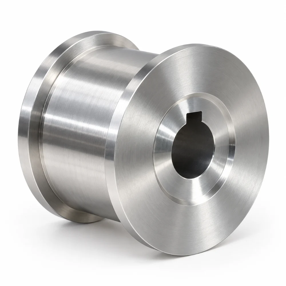
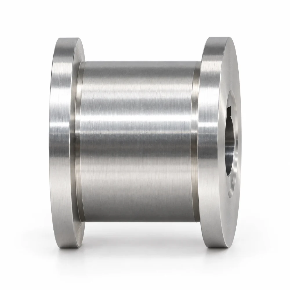
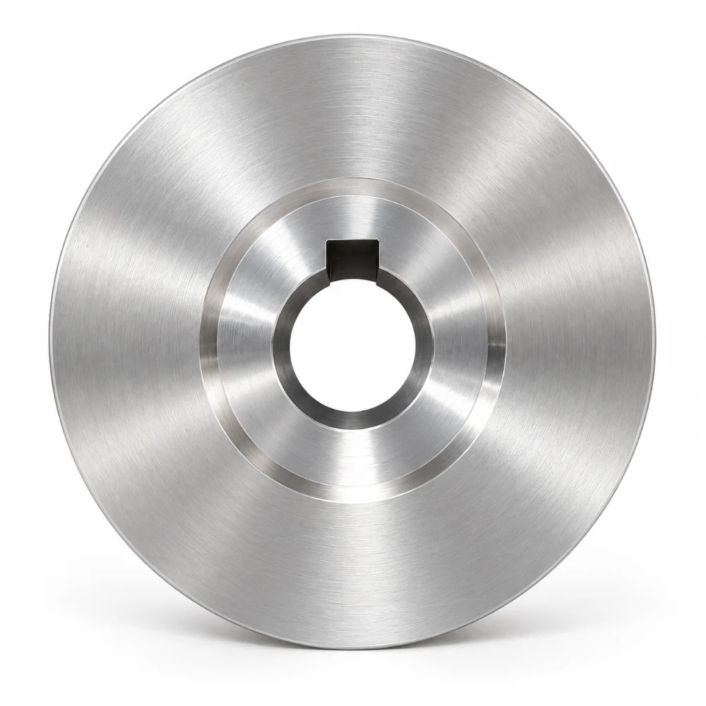


Aluminum Flanged Pulley CNC Machining for Carriage Assemblies
This Aluminum Flanged Pulley is a custom precision-machined component designed for a mechanical carriage assembly. Manufactured from 6061-T6/T651 aluminum, the part features a cylindrical center section, two raised end flanges, and a precision-machined central bore with an internal keyway.
The component combines CNC turning with rotary broaching to produce its circular geometry and internal drive feature. Its drawing specifies an outer diameter of 64.95 mm, an overall length of 38.00 mm, and a surface roughness requirement of Ra 1.6 μm. Accurate control of the bore, flange geometry, and keyway is essential for maintaining proper alignment with the mating shaft.
-
Product Name: Aluminum Flanged Pulley
-
Material: Aluminum 6061-T6 / T651
-
Manufacturing Process: Precision CNC Turning and Rotary Broaching
-
Dimensional Tolerance: ±0.002″ (approximately ±0.05 mm), subject to individual drawing requirements
-
Surface Finish: Ra 1.6 μm
-
Main Features: Dual Flanges, Cylindrical Center Body, Keyed Central Bore
-
Application: Mechanical Carriage Assembly
-
Production Type: Custom Precision Machined Parts
 Get Free Quote


Why the Flanged Geometry Matters
Unlike a conventional cylindrical spacer or simple machined sleeve, this pulley has two circular flanges separated by a reduced-diameter center section.
The flanges establish the lateral boundaries of the working surface, while the internal bore allows the component to be mounted on a compatible shaft. The keyway provides an additional mechanical engagement feature where the assembly requires a keyed connection.
Three geometric relationships are especially important:
- Flange-to-body alignment: Both end flanges must remain properly aligned with the central cylindrical section.
- Bore concentricity: The center hole must be positioned relative to the rotational axis of the external geometry.
- Flange spacing: The distance between the two end flanges influences the available working width and compatibility with surrounding components.
These features make the part more demanding than a basic turned cylinder. A dimensionally correct outside diameter alone is not sufficient if the bore or flange positions are inconsistent.
CNC Turning and Rotary Broaching: Two Processes, Different Purposes
The machining requirements can be divided into two distinct operations.
Turning the Pulley Profile
Precision CNC turning is the primary process for generating the circular external profile.
The turning sequence must account for the larger end flanges, the smaller center diameter, and the transitions between these features.
Particular attention is required around the flange shoulders. Sharp dimensional transitions can introduce unwanted tool marks or edge defects if cutting conditions are not properly controlled.
The manufacturing approach therefore needs to consider tool accessibility, secure workholding, and the relationship between the external diameters and the central bore.
Machining the Internal Keyway
The internal keyway is one of the distinguishing features of this Aluminum Flanged Pulley.
The engineering drawing specifically calls for rotary broaching, rather than treating the bore as a simple drilled opening.
This additional operation introduces several manufacturing considerations:
- Maintaining the specified keyway profile within the bore.
- Controlling the keyway position relative to the central axis.
- Preventing excessive burr formation around the broached opening.
- Verifying compatibility with the intended keyed shaft.
- Avoiding damage to previously machined surfaces during secondary operations.
Because the keyway is an assembly interface, inspection must consider its functional fit rather than its appearance alone.
Technical Specifications of the Aluminum Flanged Pulley
| Parameter | Specification |
|---|---|
| Product Name | Aluminum Flanged Pulley |
| Drawing Description | MECH. FAB. PULLEY, CARRIAGE |
| Material | Aluminum 6061-T6 / T651 |
| Overall Dimensions | 64.95 × 64.95 × 38.00 mm |
| Outer Flange Diameter | Ø64.95 mm |
| Central Body Diameter | Ø58.00 mm |
| Overall Axial Length | 38.00 mm |
| Machining Process | CNC Turning, Boring, Rotary Broaching |
| Internal Feature | Central Bore with Keyway |
| Precision Requirement | ±0.002″ (approximately ±0.05 mm) |
| Surface Roughness | Ra 1.6 μm |
| Edge Treatment | 0.50 mm Chamfer at Specified Locations |
| Surface Treatment | Standard, As-machined |
| Material Documentation | Material Certification Required |
| Inspection | Drawing-Based Dimensional Inspection |
| Documented Quantity | 8 Pieces |
| Application | Mechanical Carriage Pulley Assembly |
Note: The precision requirement is taken from the project specification. Individual feature dimensions and tolerances must follow their respective engineering drawing callouts. The 8-piece quantity is the documented project quantity, not a minimum order requirement.
Managing Concentricity Across the Two Flanges
One of the main engineering considerations is keeping the external pulley surfaces aligned with the internal bore.
The component has a relatively short overall length but combines several concentric diameters. Differences in workholding or machining setups can affect the relationship between these surfaces.
For this geometry, the machining plan should establish consistent reference surfaces and minimize unnecessary repositioning wherever possible.
Important areas for dimensional verification include the outer diameter, center body diameter, axial flange positions, and bore alignment.
This is particularly relevant for components that will rotate in a carriage mechanism. Geometric deviations can influence running accuracy even when individual diameters fall within their specified size limits.
What Should Be Checked Before the Pulley Enters Assembly?
The inspection strategy for this part differs from that of a simple rectangular mounting block.
Instead of focusing mainly on hole-to-hole distances or flatness, the pulley requires closer attention to rotational geometry and the internal shaft interface.
1. Outside Diameter and Flange Profile
Verify the major outside diameter and the dimensional relationship between the end flanges and the central cylindrical section.
2. Bore and Keyway Geometry
Check the central opening and broached keyway against the required profile and tolerance. Suitable functional gauging may be used where an appropriate mating gauge is available.
3. Runout and Concentricity
Where specified by the drawing or assembly requirements, verify that the pulley surfaces are correctly related to the bore axis.
4. Machined Surface Condition
Inspect the turned surfaces for machining marks, burrs, scratches, and edge defects. Surface roughness should be checked against the Ra 1.6 μm requirement where applicable.
5. Material and Traceability
Confirm the material designation and required certification documents as part of the manufacturing records.
A drawing-based inspection approach helps identify potential assembly issues before the component is installed in the carriage mechanism.
Engineering Considerations for Similar Custom Pulleys
This project illustrates an important distinction between a standard pulley and a drawing-specific precision component.
When sourcing a custom pulley, engineering teams should define more than the overall diameter and material grade.
The shaft interface, flange dimensions, working surface, manufacturing process, and inspection criteria may all influence the suitability of the finished component.
For similar CNC machined aluminum pulleys, the design can be reviewed in relation to:
- Required pulley and flange diameters.
- Center bore diameter and shaft compatibility.
- Keyway or other torque-transmission features.
- Running-surface dimensions and profile.
- Material grade and temper.
- Required surface finish and dimensional tolerances.
- Prototype quantity and subsequent production requirements.
Where the pulley forms part of a moving carriage, the relationship between these features should be considered alongside the surrounding assembly.
Frequently Asked Questions
1. What is an Aluminum Flanged Pulley used for?
An Aluminum Flanged Pulley is a circular mechanical component with raised edges that can help define the working path of a belt, cable, or other compatible moving element, depending on its design. This particular component is specified for a mechanical carriage assembly.
2. Why is 6061-T6 aluminum suitable for CNC machined pulleys?
6061-T6 aluminum offers a useful balance of machinability, strength, and relatively low weight. It can be CNC turned into accurately controlled cylindrical shapes and machined with additional features such as bores, keyways, and flanges.
3. Why does this pulley require rotary broaching?
The engineering drawing specifies rotary broaching for the internal keyway feature. This process is intended to create the required internal profile for engagement with a compatible shaft. The final feature must be inspected against the drawing.
4. Can CNC turning produce both flanges and the center section?
Yes. CNC turning is well suited to coaxial features such as pulley flanges, cylindrical running surfaces, and stepped profiles. Additional machining may be required for non-circular internal features.
5. What information is needed to manufacture a custom aluminum pulley?
A manufacturing review typically requires a 2D engineering drawing or 3D CAD model, material specification, external and internal dimensions, shaft connection details, tolerance requirements, surface finish, and planned order quantity.




