
 Contact Us
 Home / /


Copper Mounting Plate – Precision CNC Milling of C110 Copper
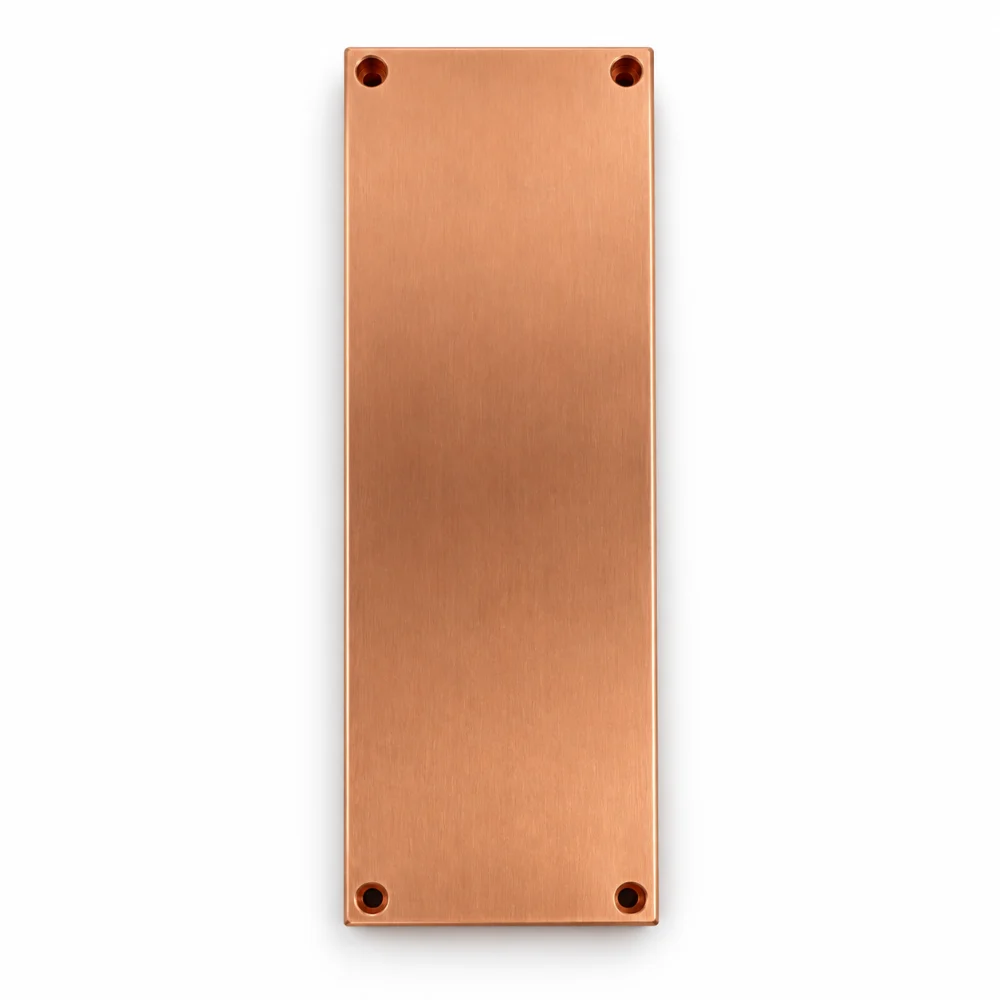
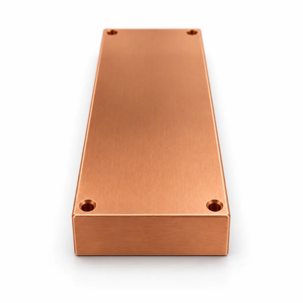
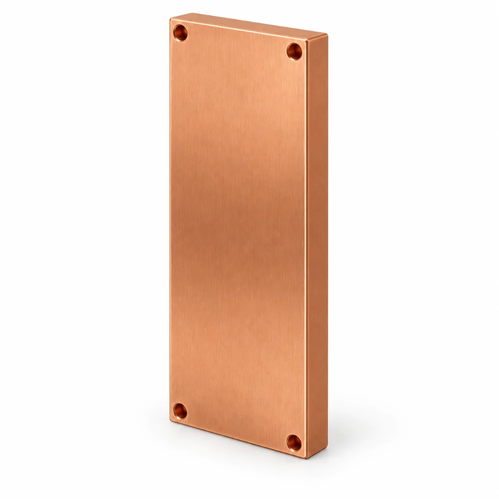
This Copper Mounting Plate is a custom precision CNC machined component designed for equipment assemblies requiring a flat mounting surface and accurately positioned fastening holes.
Made from C110 copper, the plate features a rectangular body measuring 72.0 × 22.0 × 8.0 mm, with four corner mounting holes and a clean metallic finish. Its straightforward geometry places particular importance on maintaining surface flatness, consistent hole spacing, and dimensional stability during machining.
The engineering requirements include precision tolerances for designated features, specified flatness control, and a fine surface finish at selected locations.
-
Product Name: Copper Mounting Plate
-
Material: C110 Copper
-
Manufacturing Process: Precision CNC Milling, Drilling, and Deburring
-
Overall Dimensions: 72.0 × 22.0 × 8.0 mm
-
Mounting Features: Four Ø2.000 mm Holes
-
Precision Requirement: Tighter than ±0.001″ for designated features
-
Surface Finish: Standard Machined Copper Finish
-
Production Type: Custom CNC Machined Copper Component
 Get Free Quote


Why a Simple Copper Plate Requires Careful Machining
At first glance, this component appears to be a straightforward rectangular copper plate with four mounting holes. However, its dimensional requirements introduce several considerations that are particularly relevant to copper machining.
C110 copper is valued for its excellent electrical and thermal conductivity. Compared with many common structural metals, its relatively soft and ductile characteristics also require attention during workholding, cutting, and handling.
For this part, the challenge is not complex three-dimensional geometry. It is preserving the intended flatness and dimensional relationships across a relatively broad, machined surface.
Excessive clamping pressure can distort softer material, while unsuitable cutting conditions may leave raised edges around drilled holes. Both issues can affect the quality of a precision mounting interface.
The manufacturing approach therefore emphasizes stable workholding, suitable cutting parameters, and careful surface inspection.
Four Mounting Holes and Their Role in Assembly Accuracy
The mounting-hole arrangement is one of the defining features of this component.
The design specifies four Ø2.000 mm holes positioned near the corners of the plate.
The horizontal center-to-center distance is 68.0 mm, while the vertical spacing is 18.0 mm. The nominal hole-center offset from the adjacent edges is 2.0 mm.
This arrangement leaves relatively narrow material margins around the holes, making accurate drilling and edge quality important.
During CNC machining, the hole pattern should be established from consistent reference edges. This helps preserve the relationship between the holes and the external profile.
Inspection should verify:
- Hole diameters against the specified dimensions
- Horizontal and vertical hole-center distances
- Hole positions relative to the plate edges
- Burr-free openings and suitable hole-edge conditions
- Compatibility with the intended mating components
Accurate hole positioning helps reduce potential alignment problems during assembly.
Controlling Flatness on a C110 Copper Surface
Surface flatness is an important consideration for this mounting plate.
The engineering drawing includes a 0.050 mm flatness requirement at indicated surfaces. This is particularly relevant when a plate needs to sit evenly against another component.
Copper can deform under excessive workholding pressure. Machining stresses and uneven material removal may also influence the final geometry.
For this reason, an appropriate process involves supporting the workpiece evenly, controlling cutting loads, and checking the part after release from the fixture.
The broad faces require attention not only during machining but also during handling and packaging. Local dents or raised burrs can affect how the plate contacts a mating surface.
By treating flatness as a functional characteristic rather than merely a cosmetic requirement, the machining process can better support the assembly needs of the finished component.
Surface Quality and Edge Finishing
Unlike decorative copper products, the emphasis in this case is on a consistent machined surface suitable for an engineered mounting component.
The drawing identifies Ra 0.8 μm roughness requirements at selected locations.
Achieving the specified surface condition requires suitable tooling and finishing parameters, particularly because copper can develop smeared edges or visible handling marks.
The machining and finishing considerations include:
- Maintaining consistent tool engagement across broad surfaces
- Minimizing machining marks that could affect specified contact areas
- Removing burrs from the four mounting holes
- Protecting finished faces from scratches and dents
- Cleaning away machining oil, lubricant, and loose particles before packaging
The standard surface finish retains the characteristic appearance of copper without specifying an additional plating treatment.
Detailed Technical Specifications
| Parameter | Specification |
|---|---|
| Product Name | Precision CNC Machined Copper Mounting Plate |
| Material | C110 Copper |
| Part Geometry | Rectangular Flat Plate |
| Overall Dimensions | 72.0 × 22.0 × 8.0 mm |
| Manufacturing Process | CNC Milling, Facing, Drilling, and Deburring |
| Mounting Hole Quantity | 4 |
| Mounting Hole Diameter | Ø2.000 mm |
| Horizontal Hole Spacing | 68.0 mm |
| Vertical Hole Spacing | 18.0 mm |
| Nominal Hole Edge Offset | 2.0 mm |
| Critical Precision Requirement | Tighter than ±0.001″ (approximately ±0.025 mm) for designated features |
| Specified Flatness | 0.050 mm at indicated surfaces |
| Specified Surface Roughness | Ra 0.8 μm at designated locations |
| Surface Treatment | Standard Finish |
| Inspection | Dimensional, Hole Position, Flatness, and Surface Verification |
| Reference Quantity | 10 Pieces |
| Manufacturing Type | Custom Precision CNC Machining |
Note: Individual feature tolerances and geometric requirements are governed by the approved engineering drawing. The tolerance values above should not be interpreted as applying uniformly to every dimension.
Inspection Priorities for the Finished Copper Plate
The quality of this component depends on more than its overall length, width, and thickness.
Four areas deserve particular attention during inspection.
1. Overall dimensions and material thickness
The external geometry must remain within the specified dimensional limits. Thickness should be checked at appropriate locations to identify unwanted variation.
2. Mounting-hole pattern
The four holes should be inspected for diameter, center spacing, and position relative to the external edges.
3. Flatness of designated surfaces
Appropriate measurement methods should be used to evaluate the indicated flatness requirements after machining and removal from the fixture.
4. Surface condition
The finished part should be examined for burrs, scratches, handling damage, and machining residue. Surface roughness should be verified where specified.
The drawing also calls for standard inspection documentation and cleaning before the part is placed in protective packaging.
Where Precision Copper Mounting Plates May Be Used
The final equipment application is not identified in the available specifications. However, similar machined copper plates may be suitable for designs involving:
- Electrical equipment mounting interfaces
- Conductive mechanical assemblies
- Thermal contact or heat-transfer components
- Custom equipment support plates
- Industrial fixtures requiring copper components
Their suitability depends on the actual electrical, thermal, mechanical, and fastening requirements of each assembly.
Frequently Asked Questions
1. Why use C110 copper for a CNC machined mounting plate?
C110 copper offers excellent electrical and thermal conductivity. It is suitable for custom components where these properties are beneficial, although its softer characteristics require appropriate machining and handling methods.
2. What is the mounting-hole configuration of this copper plate?
The plate features four Ø2.000 mm holes with nominal center-to-center spacing of 68.0 mm horizontally and 18.0 mm vertically.
3. Why is flatness important for a copper mounting plate?
Flatness affects how evenly the component contacts a mating surface. Uneven contact may create assembly gaps or localized loading, depending on the application.
4. Can CNC milling achieve a fine surface finish on copper?
Yes. With suitable cutting tools, machining parameters, and workholding, CNC milling can produce fine surface finishes on copper. The achievable roughness depends on the material, geometry, and designated surface requirements.
5. Can the hole pattern and plate thickness be customized?
Yes. The plate dimensions, material grade, mounting-hole locations, and surface requirements can be evaluated for customization according to the intended assembly and engineering specifications.




