
 Contact Us
 Home / /
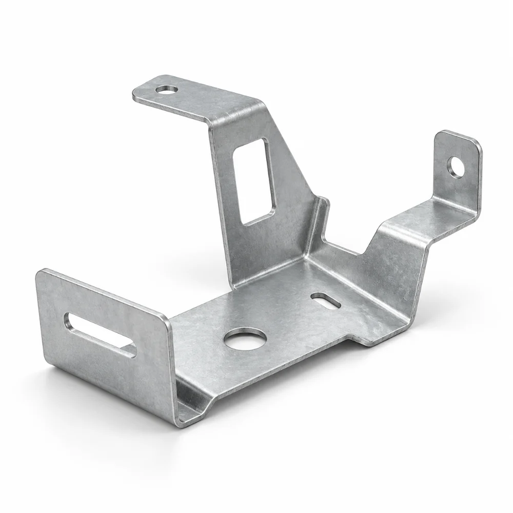


Custom Galvanized Steel Mounting Bracket with Multi-Bend Design
A Galvanized Steel Mounting Bracket with multiple bends offers a practical way to connect components positioned at different heights, angles, or mounting locations. Compared with a simple angle bracket, its formed structure can incorporate offset surfaces, mounting tabs, and locating features within a compact assembly.
This application example focuses on multi-bend sheet metal fabrication, including flat-pattern development, CNC bending sequences, hole positioning, and zinc coating protection. These considerations help engineers prepare custom bracket designs for industrial equipment.
-
Component Type: Custom Multi-Bend Mounting Bracket
-
Material: Galvanized Steel
-
Manufacturing Process: Laser Cutting and CNC Bending
-
Surface Finish: Natural Zinc-Coated Surface
-
Design Features: Multiple Bends, Mounting Flanges and Custom Cutouts
-
Tolerance: According to Approved Engineering Drawings
-
Typical Applications: Equipment Frames, Electrical Enclosures and Industrial Assemblies
-
Customization: Geometry, Thickness, Hole Layout and Bend Configuration
 Get Free Quote


Engineering a Multi-Bend Sheet Metal Bracket
A multi-bend sheet metal bracket must connect several mounting surfaces while maintaining dimensional compatibility with surrounding components.
The challenge is not simply producing individual bends. Each forming operation changes the position of features created earlier in the process.
A successful design therefore requires coordinated planning of bend locations, material behavior, mounting-hole positions, and inspection datums.
Flat-Pattern Development and Bend Allowance
Before fabrication, the finished 3D geometry is converted into a flat pattern.
Bend allowance calculations consider material thickness, bend radius, and the material's forming behavior. Accurate development helps ensure that the final bracket dimensions correspond to the approved design.
For components with several bends, the flat pattern should also be reviewed for tool clearance and possible interference during forming.
CNC Bending Sequence Planning
The order of bending operations affects whether a part can be formed without colliding with press-brake tooling.
Depending on the geometry, smaller flanges or internal bends may need to be completed before larger surrounding features.
Tool selection and bend sequencing should be established before production, particularly for brackets containing closely spaced bends or offset mounting surfaces.
Mounting Hole Alignment
Hole positions must be controlled relative to the final formed geometry.
Features located on different flanges may need to align with separate mating components. Establishing suitable reference datums helps prevent misalignment caused by accumulated bend variation.
Where necessary, selected holes may be finished after forming to meet demanding assembly requirements.
Galvanized Steel: Material and Coating Considerations
Galvanized steel has a zinc-based protective layer that improves corrosion resistance in suitable environments.
For pre-galvanized sheet metal, the coating condition must be considered during cutting and forming. Tight bends can strain the zinc layer, while cut edges expose the underlying steel.
The selected material grade, coating type, bend radius, and intended service environment should be reviewed together.
Manufacturing Considerations
1. Zinc Coating Integrity
Bend geometry should be evaluated to reduce excessive coating strain, cracking, or flaking.
2. Bend Clearance
Adequate spacing between bends helps avoid tool interference and unintended deformation.
3. Cut Edge Protection
Exposed edges may require additional treatment depending on corrosion requirements and environmental exposure.
4. Hole-to-Bend Distance
Holes positioned too close to bends can become distorted during forming. Appropriate spacing or secondary processing may be necessary.
5. Dimensional Stack-Up
Multiple bends can accumulate dimensional variation. Critical finished dimensions should be measured from defined datums.
6. Assembly Accessibility
Flanges, slots, and mounting holes must allow sufficient space for fasteners, tools, and mating components.
Recommended Fabrication Workflow
| Manufacturing Stage | Main Consideration |
|---|---|
| Drawing Review | Identify critical interfaces, datums and bend requirements |
| Material Selection | Confirm steel grade, thickness and zinc coating |
| Flat-Pattern Preparation | Calculate bend allowance and relief geometry |
| Laser Cutting | Produce the outline, mounting holes and cutouts |
| CNC Bending | Follow a planned sequence with suitable tooling |
| Edge Finishing | Remove burrs and assess exposed zinc-coated edges |
| Dimensional Inspection | Verify critical formed dimensions and hole positions |
Multi-Bend Bracket Design Specifications
| Parameter | Design Recommendation |
|---|---|
| Material | Pre-Galvanized Steel, Grade to Be Confirmed |
| Sheet Thickness | Defined by Load and Drawing Requirements |
| Forming Method | CNC Press-Brake Bending |
| Cutting Method | Laser Cutting or CNC Punching |
| Bend Radius | Selected for Material and Coating Condition |
| Mounting Features | Holes, Slots, Tabs and Cutouts as Required |
| Surface Protection | Existing Zinc Coating; Additional Protection if Specified |
| Dimensional Tolerances | Defined by Approved Drawing |
| Quality Inspection | Formed Dimensions, Hole Positions and Coating Condition |
Potential Applications
Electrical and Control Enclosures
Multi-bend brackets can create offset mounting positions for internal components, cable-management hardware, and other enclosure fittings.
Industrial Automation Equipment
Custom formed brackets may support sensors, small mechanical assemblies, and equipment accessories positioned at different heights.
Telecommunications Equipment
Compact multi-flange components can provide mounting positions inside compatible cabinets and equipment housings.
Equipment Frames and Support Structures
Galvanized steel brackets may be considered for connecting structural accessories to fabricated frames where the material and load requirements are appropriate.
These are typical application possibilities, not verified end uses of a specific customer order.
How to Improve Multi-Bend Bracket Manufacturability
A design-for-manufacturing review can help reduce unnecessary processing and assembly difficulties.
Engineers should identify the most important mounting surfaces first, then arrange bends and secondary features around those functional requirements.
Where practical, maintaining consistent bend radii, allowing sufficient flange clearance, and limiting unnecessary close-spaced bends can simplify manufacturing.
For parts requiring precise alignment between several mounting locations, the drawing should clearly distinguish critical dimensions from general dimensions.
Explore Karry Precision's Sheet Metal Fabrication Services for custom cutting, bending, and forming capabilities.
Frequently Asked Questions
1. What is a multi-bend galvanized steel bracket?
It is a sheet metal mounting component formed through multiple bending operations. The design can include offset surfaces, mounting flanges, holes, and cutouts to suit specific equipment assemblies.
2. Can galvanized steel be formed using CNC bending?
Yes. Suitable galvanized steel grades can be formed with CNC press-brake equipment. Bend radius, material thickness, coating type, and forming direction should be considered to reduce damage to the zinc layer.
3. How are dimensions controlled on parts with multiple bends?
Dimensional control begins with accurate flat-pattern development and a suitable bending sequence. Critical dimensions should be referenced to defined datums and verified after forming.
4. Do galvanized steel brackets need additional surface treatment?
Not always. The existing zinc coating may provide sufficient protection for some applications. However, exposed cut edges, coating damage, and demanding environments may require additional protective measures.
5. What drawings are required for custom multi-bend sheet metal fabrication?
A 3D CAD model and a dimensioned 2D drawing are recommended. The drawing should identify material grade, thickness, bend angles, critical tolerances, mounting-hole positions, and coating requirements.
6. Can one multi-bend bracket replace several assembled brackets?
In some designs, a single formed component can replace multiple joined parts. This depends on bend accessibility, structural loads, available space, and manufacturing feasibility.




