
 Contact Us
 Home / /
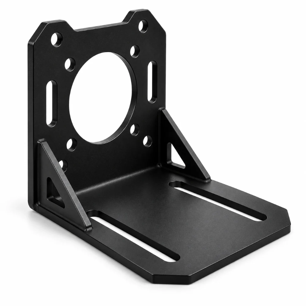
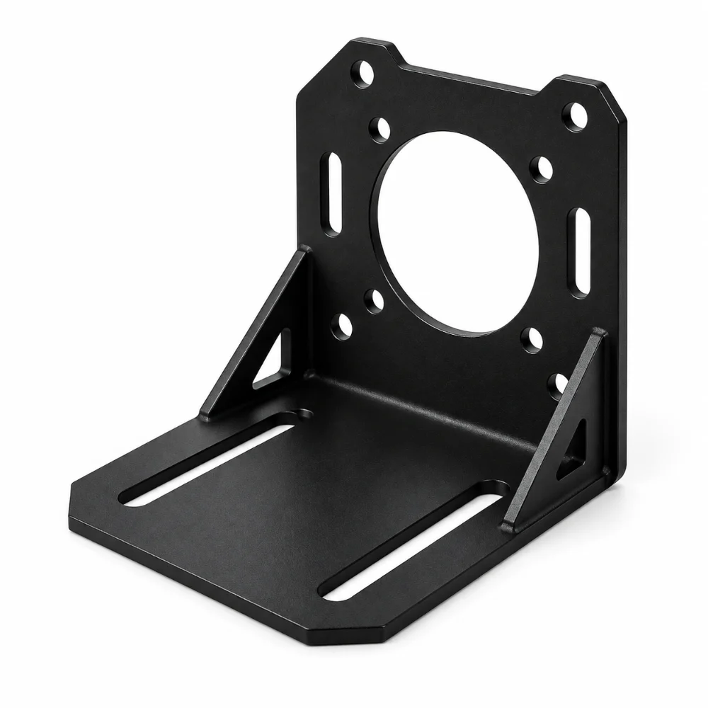


Sheet Metal Motor Mounting Bracket with Black Powder Coating
A sheet metal motor mounting bracket provides a connection between an electric motor and its supporting frame. For custom equipment, the bracket design must account for mounting-hole positions, available installation space, motor loads, and the required surface finish.
An L-shaped steel bracket offers a practical mounting arrangement where the motor and equipment frame connect at different angles. This technical application example explains how sheet metal cutting, bending, and powder coating can be planned for custom motor mounting components.
-
Component Type: Custom L-Shaped Motor Mounting Bracket
-
Material Options: Low-Carbon Steel / SPCC Steel
-
Manufacturing Methods: Laser Cutting, CNC Bending and Deburring
-
Surface Finish: Black Powder Coating
-
Mounting Features: Custom Holes and Optional Adjustment Slots
-
Typical Applications: Industrial Motors, Automation Equipment and Conveyors
-
Tolerance Requirements: According to Approved Drawings
-
Customization: Material Thickness, Dimensions, Hole Layout and Coating
 Get Free Quote


Designing a Sheet Metal Bracket for Motor Installation
The performance of a motor mounting bracket depends on more than material thickness. The mounting geometry must support the motor while maintaining alignment with the connected mechanical components.
For a typical L-shaped bracket, engineering review should focus on three areas.
Motor Interface
The mounting face should match the motor's bolt pattern and available installation clearance. Hole spacing, fastener size, and the distance between the motor body and surrounding equipment must be considered.
Bend Geometry
The bend radius, material thickness, and springback influence the final angle and mounting position. Specifying critical dimensions relative to the finished bend helps reduce assembly issues.
Installation Adjustment
Slotted holes may provide positioning flexibility during installation. However, their length, width, and distance from the material edges must be evaluated against the applied loads and fastening requirements.
Sheet Metal Fabrication Process
Laser Cutting and Hole Preparation
The process typically begins with preparing a flat pattern from the approved design.
Laser cutting can form the bracket outline, mounting holes, and adjustment slots. The flat pattern should account for bend allowance and any features located close to the bend.
Where tighter hole tolerances are required, secondary drilling or other finishing operations may be considered.
CNC Bending and Angle Control
Press-brake bending creates the required L-shaped geometry.
Material grade, sheet thickness, tooling, and bend radius affect the finished angle. Checking the location of mounting holes after bending is particularly important when the bracket connects two accurately positioned assemblies.
Deburring and Edge Preparation
Cut edges and mounting holes should be reviewed for burrs before finishing.
Deburring reduces sharp edges and helps prevent interference during handling and assembly. Edge preparation can also improve coating coverage around exposed sheet metal edges.
Black Powder Coating
Black powder coating creates a protective finish on the formed steel component.
Before coating, the required color, appearance, surface preparation, and coating thickness should be defined. Critical holes, threads, electrical contact areas, or tight-fitting surfaces may need masking.
Because coating adds thickness, the finished dimensions must be considered when evaluating assembly clearances.
Critical Design and Quality Considerations
| Design Feature | Manufacturing Consideration |
|---|---|
| Material Thickness | Selected according to loading and stiffness requirements |
| Mounting Holes | Diameter and position matched to the motor interface |
| Adjustment Slots | Sized for installation movement and fastener clearance |
| Bend Angle | Controlled according to the approved drawing |
| Bend Radius | Matched to material and forming requirements |
| Coating Thickness | Considered for final assembly fit |
| Edge Quality | Deburring and finishing as required |
| Inspection | Hole positions, dimensions and bending accuracy |
For brackets supporting motors with vibration, reversing loads, or frequent starts and stops, engineers should also review fastener retention, fatigue loading, and structural stiffness.
Customization Options
Different motor installations require different bracket designs. A custom sheet metal solution may include:
- Alternative carbon steel or stainless steel grades
- Different sheet thicknesses and bend configurations
- Custom mounting-hole patterns
- Slotted holes for installation adjustment
- Welded reinforcement features where required
- Different powder coating colors and specifications
Karry Precision offers sheet metal fabrication services for custom metal components, including cutting, bending, welding, and finishing options.
Typical Applications
Industrial Automation: Motor mounting components for automated handling systems, assembly equipment, and machine frames.
Conveyor Systems: Brackets for supporting drive motors and related mechanical assemblies.
Packaging Machinery: Custom supports for motors installed in equipment with limited mounting space.
Robotics and Motion Systems: Fabricated mounting components for selected motorized mechanisms, subject to load and alignment requirements.
These are potential applications rather than verified end uses of a specific customer component.
Preparing a Motor Bracket Drawing for Manufacturing
| Information Required | Why It Matters |
|---|---|
| Motor Model or Mounting Pattern | Defines the mounting interface |
| Material and Thickness | Affects stiffness and fabrication |
| Bend Dimensions | Establishes the finished geometry |
| Hole and Slot Specifications | Supports accurate installation |
| Surface Finish | Defines coating and masking needs |
| Required Quantity | Helps select a suitable production approach |
A complete drawing allows the manufacturing team to review potential interference, bending feasibility, and critical features before production.
Frequently Asked Questions
1. What materials are suitable for custom motor mounting brackets?
Low-carbon steel is often selected for fabricated brackets because of its strength, availability, and formability. Stainless steel and aluminum may also be considered based on weight, environmental conditions, and mechanical requirements.
2. Can L-shaped motor mounting brackets be customized?
Yes. Bracket dimensions, mounting holes, adjustment slots, material thickness, and surface finishes can be specified according to the motor and equipment design.
3. How are tolerances controlled during sheet metal bending?
Bend accuracy depends on material properties, tooling, bend radius, and process control. Critical dimensions should be identified on the engineering drawing and verified after forming.
4. Why is powder coating used on steel motor brackets?
Powder coating provides a protective and decorative finish. The level of corrosion resistance depends on surface preparation, the coating system, application quality, and service environment.
5. Can slotted mounting holes improve motor alignment?
Slotted holes can allow limited positioning adjustment during installation. Their geometry and the fastening arrangement must be designed to maintain adequate strength and secure the motor in service.
6. What information is needed to quote a custom motor bracket?
Please provide a 2D drawing or 3D model, material grade, sheet thickness, hole dimensions, coating requirements, and expected quantity. Load conditions and assembly information are also helpful when reviewing the design.
| Parameter | Standard Specification |
|---|---|
| Base Material | Cold Rolled Carbon Steel (SPCC) |
| Recommended Thickness | 2.0–5.0mm (customizable based on load requirements) |
| Cutting Process | Fiber Laser Cutting |
| Cutting Tolerance | ±0.05mm |
| Bending Process | CNC Bending |
| Bending Tolerance | ±0.1mm / ±0.3° |
| Edge Treatment | Deburring & chamfering |
| Surface Treatment | Matte Black Powder Coating (optional zinc plating, passivation) |
| Maximum Size | Customized according to drawing requirements |
| Lead Time | Prototype: 3–7 days; Mass production: 7–15 days |




