
 Contact Us
 Home / /
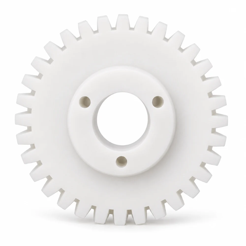
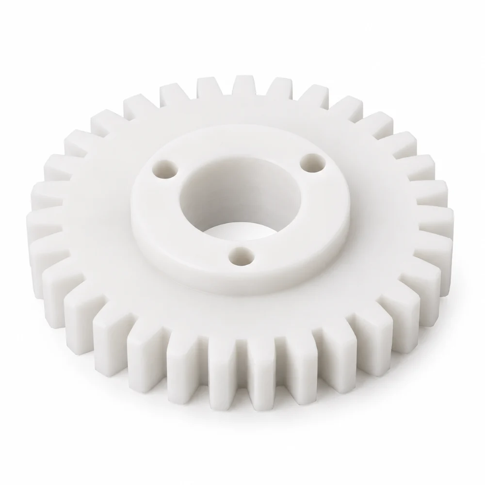
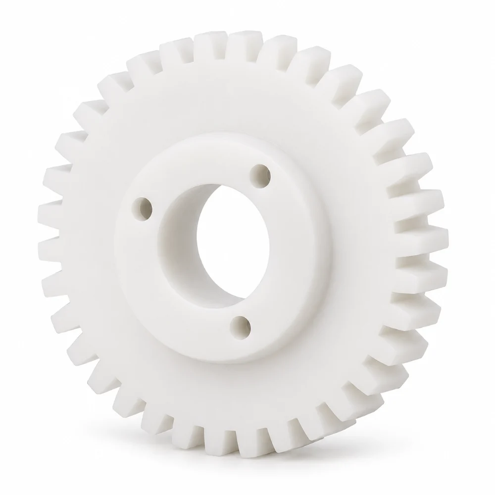


Delrin Spur Gear – Custom CNC Machined Plastic Gear with Three-Hole Hub
This Delrin Spur Gear is a custom precision-machined plastic component designed for mechanical power transmission and gear-driven assemblies. Identified as a 3 1/2 inch gear, it features evenly distributed external teeth, a central through-bore, and a raised mounting hub with three holes.
Manufactured from Delrin acetal (POM), the gear combines a lightweight polymer body with a defined tooth profile and integrated mounting features. Its construction requires careful control of gear geometry, bore alignment, and hub dimensions to support reliable engagement with mating components.
- Product Name: Delrin Spur Gear
- Material: Delrin / Acetal (POM)
- Gear Designation: 3 1/2 Inch Gear
- Part Number: UK-00329
- Manufacturing Process: Precision CNC Machining and Gear Profile Cutting
- Main Features: External Spur Teeth, Center Bore, Raised Hub, Three Mounting Holes
- Surface Finish: None Specified
- Production Type: Custom Machined Plastic Gear
 Get Free Quote


Why the Gear Hub Matters as Much as the Teeth
A distinctive feature of this Delrin Spur Gear is its raised central hub with three mounting holes arranged around the through-bore.
The external teeth are responsible for engaging the mating gear, while the center bore and hub provide the mechanical interface for installation.
These features must work together. A correctly machined tooth profile alone does not guarantee proper operation if the gear is mounted eccentrically or if the bore is misaligned with the outer toothed profile.
For this design, the critical relationship is between three functional areas: the gear's rotational center, its external tooth geometry, and the mounting interface.
Maintaining their alignment helps reduce potential assembly-related runout and uneven tooth engagement.
Machining Delrin Without Distorting the Tooth Profile
Delrin differs from steel and aluminum in several important ways. Its relatively low stiffness and higher thermal expansion require attention during cutting, clamping, and dimensional inspection.
Managing Cutting Forces
Excessive clamping pressure can temporarily deform a plastic gear blank. When the workpiece is released, elastic recovery may affect its final dimensions.
Suitable workholding should support the gear body without introducing unnecessary distortion around the center hub or the outer teeth.
Controlling Heat During Machining
Plastic machining requires careful consideration of cutting temperature. Excessive heat may affect surface quality, dimensional consistency, and the finish of narrow tooth spaces.
Sharp cutting tools, appropriate machining parameters, and efficient chip removal help maintain clean machined surfaces.
Maintaining Consistent Tooth Geometry
The tooth profile is the defining functional feature of a spur gear.
During gear cutting, attention should be given to tooth spacing, profile consistency, and the condition of the tooth roots. Burrs or irregularities along the working flanks may interfere with mating gear engagement.
Final tooth dimensions and geometry should be verified against the complete approved gear drawing.
Technical Specifications
| Parameter | Specification |
|---|---|
| Product Name | Custom Delrin Spur Gear |
| Drawing Description | 3 1/2 Inch Gear |
| Part Number | UK-00329 |
| Drawing Reference | STKDG-0020 |
| Material | Delrin (POM / Acetal) |
| Raw Material Reference | 285G08B |
| Nominal Gear Designation | 3.5 inches / 88.9 mm |
| Gear Type | External Spur Gear |
| Tooth Arrangement | Circumferential Straight Teeth |
| Center Feature | Through-Bore |
| Hub Design | Raised Circular Mounting Hub |
| Mounting Configuration | Three Holes on Hub Face |
| Machining Operations | CNC Turning, Gear Profile Machining, Drilling |
| Specified Finish | None |
| Dimensional Tolerances | According to Approved Engineering Drawing |
| Quality Verification | Tooth Geometry, Bore Size, Hub Alignment and Mounting Hole Positions |
Note: The 3.5-inch dimension is the drawing's gear designation, not a verified outside diameter or pitch diameter. Tooth count, module, pressure angle, and detailed bore dimensions must follow the complete drawing.
How the Gear Can Be Machined Efficiently
The manufacturing approach for this component can be organized around the relationship between its circular body and raised hub.
An appropriate sequence begins with preparing a Delrin blank and machining the circular reference surfaces. The central bore and raised hub can then be produced using CNC turning operations.
The external gear profile requires a machining method suitable for the specified tooth form, whether through dedicated gear cutting or appropriate CNC profile machining.
The three mounting holes are positioned relative to the gear center. Their spacing and alignment need to be maintained to support installation with the mating hub or mounting structure.
Finally, the machined gear should be cleaned, carefully deburred, and inspected after its temperature and dimensions have stabilized.
This approach is intended to control the interaction between tooth geometry, bore concentricity, and the mounting arrangement rather than treating each feature as an isolated machining operation.
Inspection Priorities for a Plastic Spur Gear
Inspection of this component should go beyond measuring the outer diameter.
Tooth Profile and Spacing
The external teeth should be evaluated against the specified gear geometry. Consistent spacing and properly finished tooth surfaces are important for meshing with a matching gear.
Center Bore and Hub Alignment
The center bore establishes the intended rotational axis. Its dimensional relationship with the outer gear profile should be checked to control eccentricity.
Three-Hole Mounting Pattern
The mounting holes should be checked for diameter and positional accuracy relative to the central axis, using the applicable drawing requirements.
Surface and Edge Condition
Gear teeth, bore entrances, and mounting holes should be free from problematic burrs, loose machining debris, and unintended edge damage.
Dimensional Stability
Because Delrin responds to temperature and mechanical loading differently from metals, inspection conditions should be consistent when verifying precision dimensions.
Where a Custom Delrin Spur Gear May Be Used
Delrin spur gears can be considered for compact mechanical assemblies in which low weight, corrosion resistance, and polymer-tooth engagement are beneficial.
Potential applications include automated positioning mechanisms, instrument drives, industrial equipment, and selected low-to-moderate-load transmission systems.
The suitability of this specific gear depends on operating speed, torque, mating materials, temperature, lubrication conditions, and the overall design of the gear train.
Its three-hole raised hub provides an installation arrangement that may be useful when the gear must be secured to a separate rotating component.
What This Case Demonstrates
This project illustrates an important principle in custom plastic gear machining: dimensional accuracy must be maintained across the entire rotational assembly, not only at the external teeth.
The Delrin material, integrated mounting hub, and central bore introduce different engineering considerations from those involved in conventional metal CNC parts.
By considering tooth geometry, workholding, center alignment, and mounting accuracy together, a manufacturing plan can be developed around the gear's actual functional requirements.
At Karry Precision, custom plastic gear projects can be evaluated using detailed 2D drawings and 3D CAD models to determine suitable machining methods, tolerances, and production requirements.
Frequently Asked Questions
1. What is a Delrin spur gear?
A Delrin spur gear is a straight-toothed gear made from acetal engineering plastic. It can be used in suitable mechanical transmission systems where low weight, corrosion resistance, and good machinability are desirable.
2. Why is Delrin used for CNC machined gears?
Delrin provides good dimensional stability compared with many general-purpose plastics, low friction characteristics, and useful wear resistance. Its suitability depends on the loading and operating conditions of the gear assembly.
3. What is the purpose of the three mounting holes?
The three-hole pattern provides a mechanical mounting interface around the center bore. The actual fastener arrangement and attachment method depend on the assembly design.
4. Can Delrin spur gears be CNC machined to custom dimensions?
Yes. Custom gear blanks, center bores, mounting hubs, and external tooth profiles can be machined according to defined engineering requirements. The achievable tolerances depend on the material, gear geometry, tooling, and inspection method.
5. What information is required for custom spur gear manufacturing?
A complete drawing should define the gear size, number of teeth, module or diametral pitch, pressure angle, tooth width, bore dimensions, mounting pattern, tolerances, and material requirements.




