
 Contact Us
 Home / /
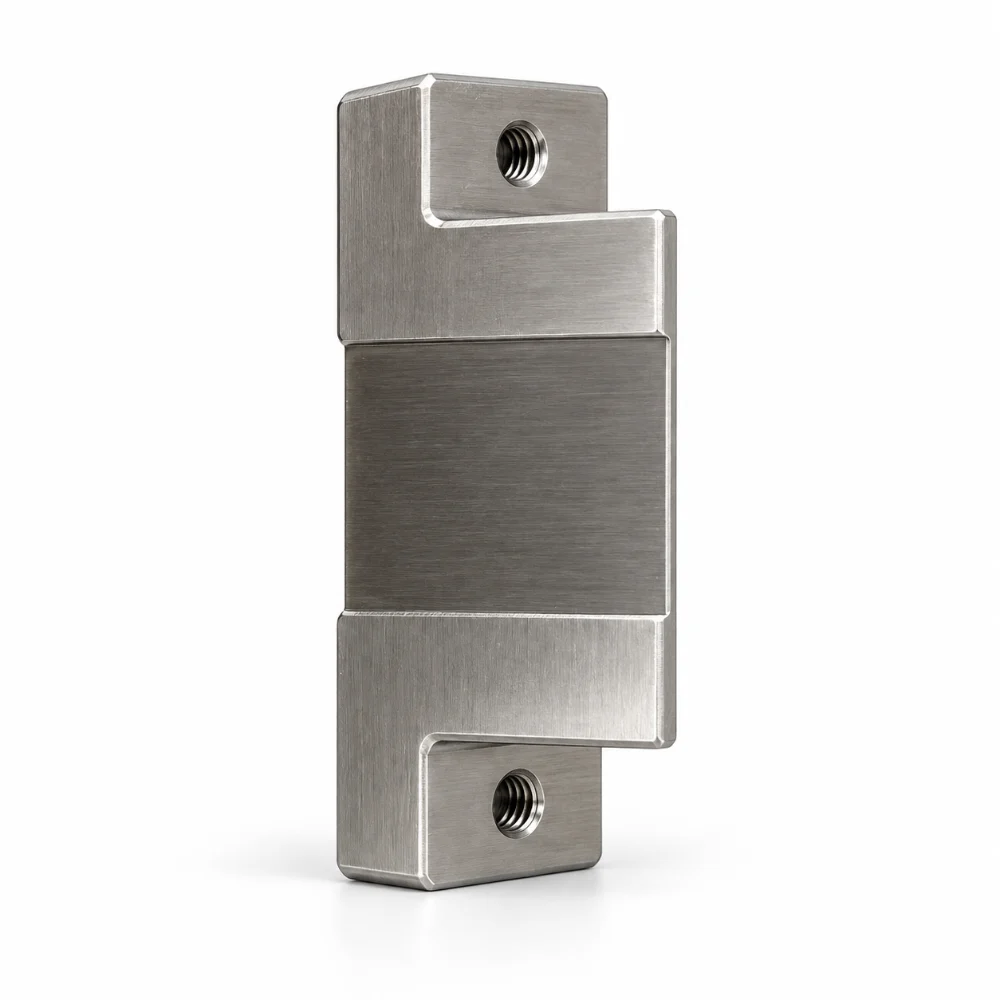
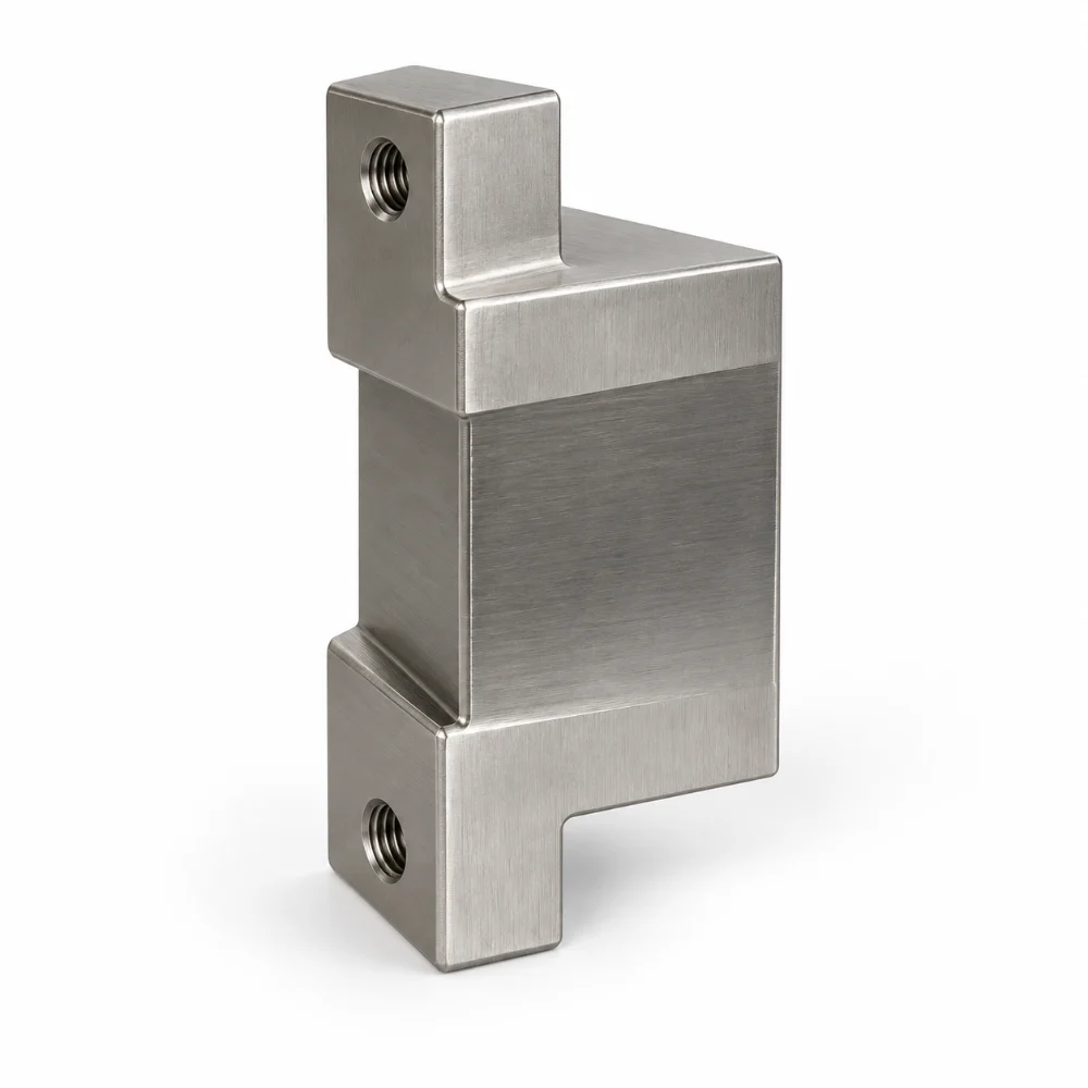


Stainless Steel Mounting Bracket – Precision CNC Milling with Angled Support Geometry
This Stainless Steel Mounting Bracket is a custom precision-machined component designed for secure positioning and fastening within mechanical assemblies. Its compact construction combines two mounting ends with a recessed central section and an angled structural profile.
Made from 300-series stainless steel, the bracket features two threaded mounting holes, controlled transitions between stepped surfaces, and a machined finish. The design requires accurate hole positioning, consistent material thickness, and careful machining of the angled surfaces to maintain dimensional compatibility.
-
Product Name: Stainless Steel Mounting Bracket
-
Material: 300 Series Stainless Steel
-
Manufacturing Process: CNC Milling, Drilling and Tapping
-
Overall Dimensions: 58.42 × 20.32 × 18.52 mm
-
Critical Tolerance: ±0.001″ (approximately ±0.025 mm)
-
Mounting Features: Two 8-32 UNC Threaded Through-Holes
-
Surface Finish: Standard Machined Finish
-
Application: Custom Mechanical Mounting and Positioning Assemblies
 Get Free Quote


Why the Angled Center Section Matters
The distinctive feature of this bracket is the relationship between its two mounting ends and the recessed section connecting them.
Unlike a conventional flat mounting plate, the component incorporates a raised central profile with angled transitions. These surfaces establish the required geometry between the attachment points and the central body.
The engineering drawing specifies a 45° ±2° angle on the cross-sectional profile, together with defined corner radii. Maintaining this geometry requires more than simply machining two holes into a rectangular block.
The end mounting surfaces must remain dimensionally consistent while the intervening material is removed to create the final stepped and angled shape.
For this reason, the central recess, angled transitions, and mounting-hole locations are treated as related geometric features rather than independent machining operations.
Machining Strategy: Keeping Both Mounting Ends Consistent
Establishing Reference Surfaces
The two mounting ends form the most important reference areas for the bracket.
Accurate CNC milling begins with establishing suitable locating surfaces so that the overall profile, recessed region, and hole centers can be machined with a consistent reference system.
For a small component measuring approximately 58.42 mm in overall length, setup accuracy is important because even minor positioning errors can affect the relationship between the two mounting ends.
Controlling the Recessed Geometry
The central section introduces a machining challenge that is less common in standard rectangular brackets.
The drawing identifies a 0.768″ dimension with a unilateral tolerance of +0.000″/−0.001″ associated with the recessed region.
This requires careful control of the specified feature during material removal.
A suitable CNC milling approach uses controlled cutting passes and a stable workholding arrangement to minimize dimensional variation between the machined surfaces.
Producing the Angled Transitions
The component includes a 45° ±2° angled feature and a specified R0.050 corner radius.
These features require attention to cutter selection, toolpath geometry, and the transition between adjacent machined surfaces.
The manufacturing objective is to preserve the intended profile without introducing unwanted steps or excessive edge rounding.
Detailed Technical Specifications
| Parameter | Specification |
|---|---|
| Product Name | Stainless Steel Mounting Bracket |
| Component Reference | D01448305 |
| Material | 300 Series Stainless Steel |
| Manufacturing Process | Precision CNC Milling, Drilling and Tapping |
| Overall Dimensions | 58.42 × 20.32 × 18.52 mm |
| Overall Length | 2.300″ (58.42 mm) |
| Overall Width | 0.800″ (20.32 mm) |
| Overall Height | 0.729″ (18.52 mm) |
| Critical Recess Dimension | 0.768″ +0.000″/−0.001″ |
| Selected Location Dimension | 1.150″ ±0.001″ |
| Mounting Holes | 2 × Ø0.136″ Through, 8-32 UNC Threaded Through |
| Angled Profile | 45° ±2° |
| Typical Corner Radius | R0.030″ |
| Specified Profile Radius | R0.050″ |
| Critical Precision Requirement | ±0.001″ (approximately ±0.025 mm) |
| Surface Roughness | Ra 3.2 μm (125 μin) |
| Surface Treatment | Standard / As-Machined |
| Edge Treatment | Break All Edges and Remove Sharp Burrs |
| Inspection | Dimensional, Profile and Thread Verification |
| Production Type | Custom CNC Machined Component |
Note: The specifications above describe the drawing requirements rather than independently verified inspection results. Individual tolerances and dimensions are governed by the approved manufacturing drawing.
Threaded Hole Alignment and Assembly Fit
Although the bracket contains only two mounting holes, their position is an important part of its functional design.
Both holes are located toward the outer mounting ends, where fasteners can secure the component to a mating structure.
The drawing specifies two Ø0.136″ through-hole features with 8-32 UNC internal threads.
For this configuration, the manufacturing and inspection process should address three factors:
- Hole Position: Maintain the intended distance and alignment between the two mounting locations.
- Thread Quality: Produce clean internal threads with consistent engagement along the specified through-hole depth.
- Edge Condition: Remove burrs around the hole entrances without unnecessarily enlarging or damaging the surrounding mounting surfaces.
Thread verification with suitable gauges helps determine whether the machined holes meet the specified fastening requirements.
The combination of accurately positioned threads and controlled mounting surfaces contributes to reliable mechanical assembly.
Surface Quality Across Different Geometries
This bracket contains several surfaces with different machining characteristics.
The broad mounting faces are relatively straightforward to finish, while the recessed center, angled transitions, and small internal corners require greater attention.
The engineering requirements include a surface roughness specification of Ra 3.2 μm, equivalent to approximately 125 μin.
Rather than applying a decorative coating, the component uses a standard machined surface finish.
The final finishing process should address visible tool marks where required, maintain the specified edge geometry, and remove sharp burrs from the machined features.
Special attention is needed at the transitions between the flat mounting areas and the recessed center because excessive manual deburring could change the intended profile.
Inspection Focus: Geometry Before Appearance
For this particular bracket, visual appearance alone cannot establish whether the component meets its functional requirements.
Inspection is better organized around the geometric relationships that influence assembly.
Mounting Surface Alignment
Verify that the two mounting ends maintain their specified relative positions and that the component seats as intended against its mating surfaces.
Critical Recess Dimensions
Check the 0.768″ unilateral-tolerance feature and other controlled dimensions using suitable measurement equipment.
Angled Profile Verification
Confirm the 45° ±2° geometry and specified radii without relying solely on visual assessment.
Thread Inspection
Inspect both 8-32 UNC threaded holes for proper form, engagement, and location.
Surface and Edge Condition
Check the finished surfaces against the applicable roughness requirement and confirm that machining burrs have been removed.
These checks place the inspection emphasis on actual assembly-related features rather than applying the same inspection priorities to every CNC machined component.
Where Similar Mounting Brackets Are Used
The exact equipment associated with this component is not identified in the engineering drawing. However, brackets with similar geometry may be suitable for several types of mechanical assemblies.
Industrial Equipment Mounting
Custom brackets can help position mechanical components where standard flat mounting plates do not provide the required profile or clearance.
Precision Assembly Fixtures
Stepped mounting surfaces and threaded attachment points may be incorporated into specialized fixtures that require controlled component positioning.
Automated Machinery
Compact stainless steel brackets can support installation arrangements within equipment frames, positioning mechanisms, and other machinery structures.
Custom Mechanical Assemblies
Drawing-based CNC machining allows manufacturers to produce mounting brackets with application-specific angles, recess dimensions, hole locations, and fastening features.
Manufacturing Value of This Bracket Design
This case illustrates an important aspect of precision CNC milling: a component does not need a large number of complex features to require careful process planning.
The main manufacturing challenge lies in maintaining the relationship between a small number of important details.
For this bracket, those details are the recessed central profile, the angled geometry, the two threaded mounting locations, and the mounting surfaces at opposite ends.
Controlling these features together provides a more meaningful basis for evaluating the component than considering its external appearance alone.
At Karry Precision, custom stainless steel components can be evaluated for CNC manufacturing based on their geometry, tolerance requirements, material specifications, and intended assembly conditions.
Frequently Asked Questions
1. What is a stainless steel mounting bracket used for?
A stainless steel mounting bracket provides a mechanical connection or positioning interface between components. Its geometry, mounting holes, and material are selected according to the intended assembly.
2. Why does this bracket have an angled central section?
The angled section establishes a defined structural profile between the two mounting ends. The specific geometry may provide the clearance or positioning relationship required by its mating components.
3. Can CNC milling produce 45-degree mounting features?
Yes. CNC milling can produce angled surfaces according to specified drawing requirements. This bracket includes a 45° ±2° profile that requires appropriate machining and inspection.
4. Are threaded holes suitable for precision mounting brackets?
Yes. Threaded holes are commonly used to secure machined brackets with mechanical fasteners. The required thread specification, depth, and position depend on the assembly design.
5. Can stainless steel mounting brackets be customized?
Yes. Custom brackets can be manufactured with different dimensions, mounting-hole arrangements, recessed profiles, surface requirements, and stainless steel grades, subject to engineering review.




