
 Contact Us
 Home / /
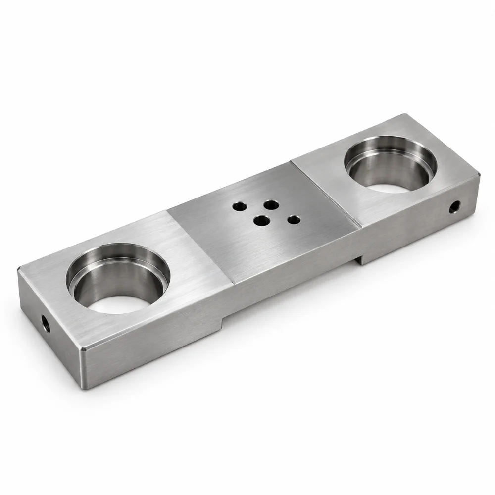
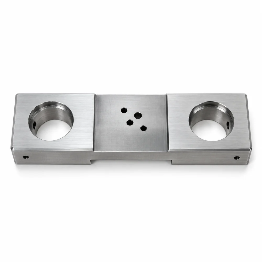


CNC Machined Steel Block for an Experimental Flow Rig Test
This CNC Machined Steel Block is a custom manufactured 34CrNiMo6 alloy steel block, linked to an experimental set up of flow rig tests. This part has a rectangular form, two large punched holes for machining, smaller holes in the center of the body, and other side holes for machining purposes.
It was stated on the drawings that the customer requires EN 10083-3 material, heat treatment specification P30-026T, and cleanliness requirements, in accordance with TI-1196, at final assembly.
In this project, the works of engineering are not limited to the exterior shaping. When preparing a component for integration into test equipment, bore alignment, access to the holes in the cross-directional direction, surface condition, and post-machining cleanliness should be considered.
-
Product Name: Custom CNC Machined Steel Block
-
Material: 34CrNiMo6 Alloy Steel
-
Material Standard: EN 10083-3
-
Manufacturing Process: CNC Milling, Drilling and Boring
-
Main Features: Dual Large Bores, Small Hole Pattern, Side Drilling and Machined Relief
-
Heat Treatment Specification: P30-026T
-
Heat Treatment Note: Gas Quench (Per Drawing)
-
Cleanliness Requirement: TI-1196 (Applicable at Final Assembly)
-
Project Application: Experimental Flow Rig Test
-
Project Type: Custom Experimental Component
 Get Free Quote


CNC Machining Requirements for the Flow Rig Steel Block
The component has a rectangular profile with machined circular features positioned at opposite ends.
Several smaller holes are located toward the middle, while an additional hole is visible on a side face. The photographs also show machined bore entrances and local stepped features.
This arrangement requires attention to machining access from different directions and the relationship between the finished surfaces.
Unlike a simple spacer or solid mounting plate, this steel block contains multiple features that may need to align with other parts in an experimental assembly.
The exact function of each opening must be established from the complete customer design.
Maintaining the Relationship Between Large Bores
The two large circular openings are prominent features of the component.
When machining similar steel blocks, the bore locations should be controlled relative to the selected datum surfaces. Consistent workholding and suitable finishing operations are important for maintaining the intended spacing and orientation.
Depending on the final drawing requirements, bore machining may involve drilling, circular interpolation, and precision boring.
Karry Precision's CNC milling services support the production of custom blocks containing machined pockets, bores, and multiple mounting features.
Side Drilling and Multi-Direction Machining
One distinguishing feature of this component is the presence of a side hole in addition to the openings on the main machined face.
Producing features from different directions introduces additional setup considerations.
A suitable machining strategy should account for:
- Reference surface selection
- Side-hole positioning
- Access to internal bore surfaces
- Edge quality at drilled openings
- Workholding during changes in machining orientation
If a side drilling intersects an internal opening, additional deburring and inspection may be necessary. The exact intersection geometry should be verified from the approved drawing rather than assumed from the photographs.
Controlling Machined Relief Features
The photographs show stepped and relieved surfaces around portions of the component.
These features may provide clearance, positioning, or assembly access, depending on the design.
During manufacturing, their dimensions should be controlled relative to the main reference faces and nearby holes.
For similar components, a well-planned sequence of rough milling, feature machining, and finishing can help maintain consistent geometry.
Material and Heat Treatment Considerations
The engineering drawing specifies 34CrNiMo6 alloy steel according to EN 10083-3.
This chromium-nickel-molybdenum alloy is commonly selected for mechanical components requiring useful strength, toughness, and hardenability.
The document also identifies P30-026T as a heat treatment specification and includes a gas-quench instruction.
Because heat treatment can introduce dimensional changes, the machining plan should establish which features require finishing before or after the specified treatment.
This is particularly relevant for blocks containing multiple holes whose positions must remain consistent.
The supplied excerpt does not provide a numerical hardness acceptance range or a completed heat treatment report. Accordingly, no achieved hardness or final heat treatment result is claimed here.
Technical Specifications
| Parameter | Specification |
|---|---|
| Component | Custom Machined Steel Block |
| Material | 34CrNiMo6 |
| Material Standard | EN 10083-3 |
| Primary Machining Method | CNC Milling |
| Additional Machining | Drilling and Boring |
| External Geometry | Rectangular Machined Body |
| Hole Configuration | Two Large Bores and Multiple Smaller Holes |
| Additional Features | Side Hole and Machined Relief |
| Heat Treatment Specification | P30-026T |
| Treatment Note | Gas Quench |
| Cleanliness Specification | TI-1196 |
| Cleanliness Stage | Final Assembly |
| Design Status | Experimental |
| Surface Coating | Not Specified in Available Drawing |
Individual dimensions, tolerances, and test-performance requirements must follow the complete approved engineering drawing.
Cleanliness Requirements for Experimental Test Components
The drawing references cleanliness specification TI-1196 and identifies final assembly as the applicable stage.
This is an important distinction for components intended for test equipment.
CNC machining can leave chips, cutting-fluid residues, and small burrs around drilled holes or internal surfaces.
For parts that have assembly cleanliness requirements, these conditions should be addressed through an appropriate cleaning and inspection plan.
Potential quality-control considerations include:
- Removing machining debris from bores and drilled holes
- Inspecting accessible internal edges for burrs
- Preventing contamination during handling
- Selecting suitable cleaning methods for the material condition
- Maintaining cleanliness through packaging and final assembly
The exact cleaning process and acceptance criteria must follow the applicable customer specification.
The drawing establishes a cleanliness requirement; it does not, by itself, confirm that a particular cleaning procedure or cleanliness test has been completed.
Inspection Considerations for Multi-Hole Steel Blocks
Dimensional verification is especially important when a block contains several features machined from different directions.
The following table outlines appropriate inspection considerations.
| Inspection Area | Main Focus |
|---|---|
| Large Bores | Diameter, profile and relative positioning |
| Central Small Holes | Hole size, location and edge condition |
| Side Hole | Diameter, position and alignment |
| Reference Faces | Flatness and dimensional relationships where specified |
| Machined Relief | Profile dimensions and clearance |
| Heat Treatment | Verification against the applicable treatment specification |
| Cleanliness | Compliance with customer-defined assembly cleanliness criteria |
Depending on the specified tolerances, inspection may involve calipers, bore gauges, height gauges, and coordinate measuring equipment.
For more information, see Karry Precision's tolerance and quality control capabilities.
Engineering Considerations for Experimental Flow Rig Components
The engineering drawing references an F3E flow rig test, but the complete operating system and internal flow path are not provided.
For similar experimental assemblies, early manufacturing reviews can help identify potential problems with hole accessibility, part positioning, machining burrs, and cleaning requirements.
It is also important to distinguish dimensional conformity from actual operating performance.
A component that meets its machining requirements still needs appropriate system-level evaluation where pressure, flow, sealing, or other functional conditions apply.
The available information does not establish pressure ratings, leak-test results, or verified fluid-flow performance for this component.
Frequently Asked Questions
What is a CNC machined steel block?
A CNC machined steel block is a custom component manufactured from steel stock using computer-controlled machining processes. Depending on its design, it may contain bores, mounting holes, milled recesses, or specialized mechanical features.
Why is 34CrNiMo6 used for steel machining projects?
34CrNiMo6 provides useful strength, toughness, and hardenability when supplied and processed in an appropriate material condition. Its suitability depends on the component's operating requirements.
What are the challenges of machining holes from multiple directions?
Multi-directional machining requires careful datum selection, workholding, and positioning. Additional attention may be needed for deburring and inspecting holes that intersect internal features.
What does gas quenching mean in heat treatment?
Gas quenching is a cooling process that uses a controlled gas medium after heating. The final material properties depend on the complete heat treatment procedure, including temperature, cooling conditions, and any subsequent tempering.
Why is cleanliness important for machined test components?
Machining debris, burrs, and residues may interfere with assembly or experimental operation. When a customer specifies cleanliness requirements, suitable cleaning and inspection methods should be established.
Can Karry Precision manufacture custom CNC machined steel blocks?
Karry Precision provides custom CNC machining services for drawing-based steel components. Material specifications, machining geometry, heat treatment, tolerances, and inspection requirements can be reviewed before production.




