
 Contact Us
 Home / /


CNC Machined Mounting Flange for Picker Wheel Gearbox Assembly
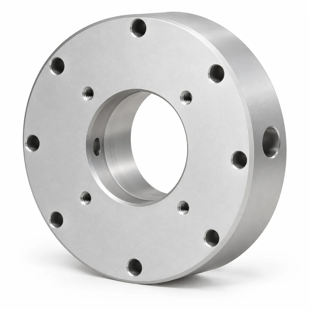
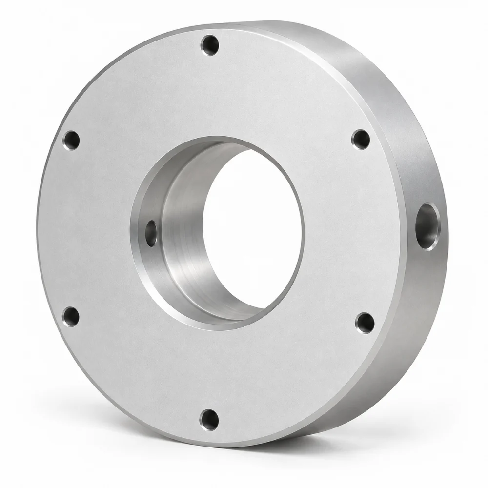
This CNC Machined Mounting Flange is a custom circular component identified in the customer engineering drawing as a gearbox mounting block for a picker wheel drive assembly. It features a large central bore, multiple mounting holes arranged around the circular body, and a radial hole machined through the outer sidewall.
The component combines rotational geometry with drilling features on different faces. Its manufacturing requirements involve controlling bore alignment, mounting hole positions, and the relationship between the central opening and external cylindrical surfaces.
-
Product Name: Custom CNC Machined Mounting Flange
-
Drawing Description: Gearbox Mounting Block, Picker Wheel Drive
-
Manufacturing Process: Precision CNC Turning, Drilling and Milling (Suggested)
-
Main Features: Circular Body, Central Bore, Mounting Hole Pattern and Radial Side Hole
-
Drawing Units: Inches
-
Drawing Revision: 00A
-
Dimensional Tolerances: As Specified on Customer Drawing
-
Material: Not Confirmed in Available Drawing
-
Surface Finish: Machined Metallic Appearance; Specification Not Confirmed
-
Manufacturing Type: Custom Drawing-Based CNC Machining
 Get Free Quote


Precision Machining for Circular Gearbox Mounting Components
The most distinctive characteristic of this component is its combination of circular geometry and mounting features machined from different directions.
The main body has a thick cylindrical profile with a large opening through its center. Multiple smaller holes are visible around the front and rear mounting faces, while an additional radial opening is positioned on the outer cylindrical surface.
Unlike a conventional flat mounting plate, this design requires the machining process to consider both axial features and sidewall access.
For similar parts, CNC turning is well suited to producing cylindrical surfaces and concentric bores, while drilling and milling operations can create mounting holes and additional installation features.
Explore Karry Precision's precision CNC turning services for circular mechanical components.
Key Manufacturing Challenges
Maintaining the Central Bore and Outer Diameter
The large central opening is one of the primary geometric features of this mounting component.
For gearbox mounting applications, the relationship between the central bore and outer cylindrical body may influence assembly positioning and clearance.
A suitable manufacturing strategy should consider:
- Central bore diameter and circularity
- Outer diameter consistency
- Alignment between internal and external cylindrical surfaces
- Front and rear face geometry
- Edge condition around the central opening
Precision turning and appropriate boring operations can help produce these features according to the specified dimensions.
Actual concentricity and geometric tolerances must follow the approved engineering drawing.
Controlling the Mounting Hole Pattern
The component contains multiple smaller holes distributed around the circular mounting surfaces.
These holes must be positioned according to their specified locations, rather than simply spaced by visual approximation.
Hole-position control is particularly important when a mounting component must align with fasteners or locating features on another assembly.
Depending on the approved drawing, machining may involve indexed drilling, CNC milling, or another suitable positioning method.
Accurate datum selection and stable workholding can help maintain the relationship between the mounting holes and central bore.
Machining the Radial Side Hole
One important feature visible in the product photographs is a radial opening through the outer cylindrical wall.
This feature requires machining access from a direction different from the main axial bore.
During manufacturing, the process plan must consider side-hole positioning, workholding orientation, drilling depth, and internal edge quality.
If the radial opening intersects the central bore, the intersection may require additional deburring and inspection.
The actual purpose of the radial hole, including whether it supports fastening, positioning, or another function, must be confirmed from the complete design.
Managing Multiple Machining Setups
Circular mounting components with both axial and radial features may require more than one machining orientation.
A practical manufacturing sequence should preserve consistent reference datums between operations.
For example, the cylindrical body and main bore may be used as reference features when planning subsequent mounting-hole machining.
However, the exact process sequence depends on the material, specified tolerances, equipment and workholding method.
Karry Precision's CNC milling capabilities support the production of additional holes, profiles and multi-face features on custom machined components.
Technical Specifications
| Parameter | Specification |
|---|---|
| Product Name | CNC Machined Mounting Flange |
| Drawing Description | Gearbox Mounting Block, Picker Wheel Drive, BIOS |
| Drawing Number | 10201525 |
| Drawing Revision | 00A |
| Drawing Size | C |
| Dimensional Units | Inches |
| Main Geometry | Cylindrical Mounting Body |
| Central Feature | Large Through-Bore |
| Additional Features | Mounting Holes and Radial Side Hole |
| Primary Machining Method | CNC Turning (Suggested) |
| Secondary Processes | Drilling and Milling (Suggested) |
| Material Grade | To Be Confirmed |
| Surface Treatment | To Be Confirmed |
| Tolerance Requirements | Customer Engineering Drawing |
| Application | Picker Wheel Drive Gearbox Assembly |
The supplied drawing excerpt identifies the application and drawing conventions but does not show complete feature dimensions or a confirmed material specification.
Quality Control for CNC Machined Mounting Flanges
The inspection plan for this type of component should focus on the geometric relationship between the central bore, mounting holes and cylindrical body.
Maintaining these relationships is important for installation and fit with mating components.
| Inspection Feature | Quality Control Focus |
|---|---|
| Central Bore | Diameter, circularity and specified geometric tolerances |
| Outer Cylindrical Surface | Diameter and relationship to the central bore |
| Mounting Hole Pattern | Hole sizes and positional relationships |
| Radial Side Hole | Diameter, location and drilling condition |
| Front and Rear Faces | Face geometry and parallelism where specified |
| Machined Edges | Burr removal and edge condition |
Depending on the applicable tolerances, inspection may involve bore gauges, micrometers, height gauges, coordinate measuring equipment and suitable dimensional gauges.
The engineering drawing uses inches as its measurement system, so inspection records should remain consistent with the approved drawing.
Learn more about Karry Precision's tolerance and quality control capabilities.
Gearbox Mounting and Mechanical Assembly Considerations
The customer drawing identifies this component as a mounting block associated with a picker wheel drive gearbox.
This provides a more specific application context than a general-purpose industrial flange.
For similar gearbox assemblies, a machined mounting component may provide an interface for locating, fastening or supporting another mechanical part.
Important design considerations can include:
- Matching the central opening to the mating component
- Aligning mounting holes with the installation interface
- Providing clearance for adjacent mechanical elements
- Maintaining stable contact between mounting faces
- Allowing access to specified side features
The supplied photographs and drawing title do not establish the actual load rating, operating speed, bearing fit or installation configuration.
These functional requirements should be confirmed during the engineering review.
Manufacturing Considerations for Repeat Orders
For repeat production, maintaining consistent relationships between multiple machining operations is important.
The manufacturer should confirm the material grade, finished dimensions, surface treatment, and inspection requirements before establishing the final machining route.
Where a component contains numerous mounting holes, a repeatable locating strategy helps reduce variation between parts.
Similarly, any specified bore fit or geometric tolerance should be evaluated against the chosen workholding and inspection methods.
The available project documentation establishes the component design and application but does not provide a verified production quantity or completed dimensional inspection report.
Frequently Asked Questions
What is a CNC machined mounting flange?
A CNC machined mounting flange is a custom mechanical component produced using computer-controlled machining processes. It may include a central bore, mounting holes, cylindrical surfaces and other features required for assembly.
Why is CNC turning suitable for circular mounting flanges?
CNC turning is well suited to manufacturing rotational features such as outer diameters, circular faces and central bores. Additional drilling or milling may be required for mounting holes and side features.
What is the purpose of the central bore?
The central bore may provide clearance, locating geometry or an interface with a mating component. Its exact function and tolerance requirements depend on the gearbox assembly design.
How are mounting holes accurately positioned?
Mounting holes can be machined using CNC drilling or milling operations referenced to suitable datums. Their diameters, locations and positional tolerances should follow the approved drawing.
Can a mounting flange include radial side holes?
Yes. Radial drilling can create openings through the cylindrical sidewall. The machining strategy should account for workholding orientation, drilling depth, possible internal intersections and burr removal.
Can Karry Precision manufacture custom gearbox mounting components?
Karry Precision provides custom CNC machining services for mounting components, flanges and other precision mechanical parts. Customers can submit 2D drawings or 3D CAD files for machining feasibility and quotation review.




