
 Contact Us
 Home / /
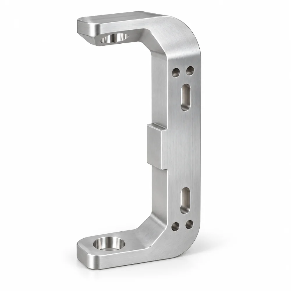
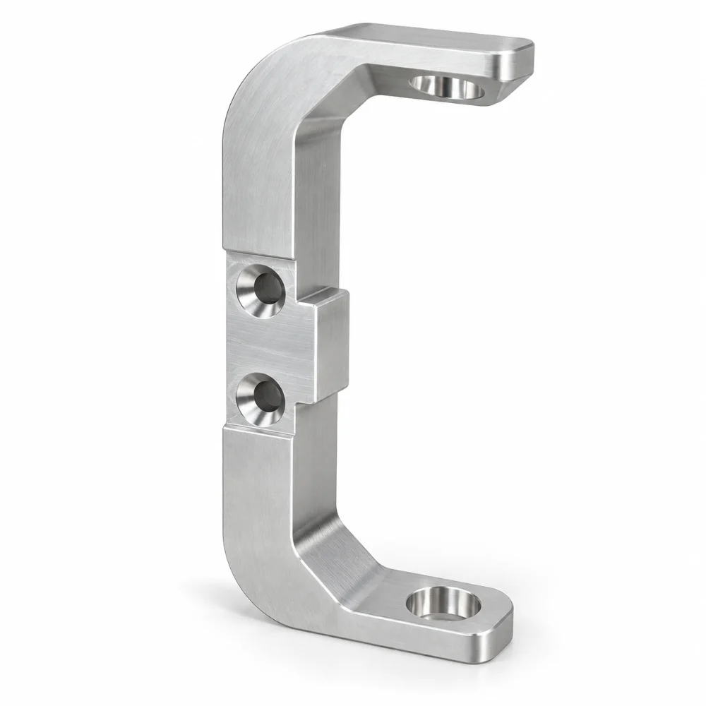
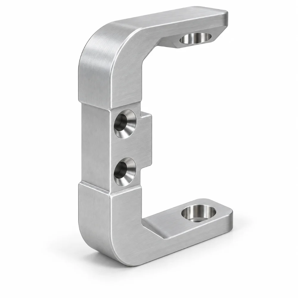


CNC Machined Aluminum U Bracket for Precision Equipment Assembly
The CNC Machined Aluminum U Bracket is a customized aluminum part for assembling a special equipment. It is identified by the customer who pulls it as a "U-Arm Defender Pre-Oven Close" and is stamped with "7075 aluminum".
U-shaped profile, two precision end mounting bores, many through-holes, long slits and countersunk fastening all come together in the component. Its overall drawing dimensions include a length of 5.830″ (148.08 mm) and a height of 2.250″ (57.15 mm).
-
Product Name: Custom CNC Machined Aluminum U Bracket
-
Material: 7075 Aluminum Alloy
-
Drawing Description: U-Arm Defender Pre-Oven Close
-
Suggested Manufacturing Process: Precision CNC Milling, Drilling and Countersinking
-
Overall Length: 5.830″ (148.08 mm)
-
Overall Height: 2.250″ (57.15 mm)
-
End Mounting Bores: 2 × Ø0.627″ +0.002″/−0.000″
-
Additional Holes: 4 × Ø0.188″ Through-Holes
-
Countersunk Features: 2 × Ø0.266″ Through-Holes with Ø0.507″ × 100° Countersinks
-
Main Features: U-Shaped Profile, Curved Corners, Elongated Slots and Multiple Mounting Interfaces
-
Surface Treatment: None Specified
-
Manufacturing Type: Custom Drawing-Based Precision Machining
 Get Free Quote


CNC Milling Challenges for a Complex U-Shaped Bracket
The distinctive feature of this component is its open U-shaped geometry.
The design combines a long connecting section with two mounting arms positioned at opposite ends. Each end contains a mounting bore, while the connecting region includes additional holes and slotted features.
This geometry introduces several manufacturing considerations that differ from conventional rectangular or cylindrical CNC machined parts.
Machining the U-Shaped Profile
The customer drawing specifies an overall length of 5.830″ and rounded transitions along the U-shaped body.
The profile includes R1.000″ typical outer corners and additional R0.125″ radius features.
For similar aluminum brackets, CNC milling allows the production of complex external profiles, internal contours, and local stepped features.
The machining strategy should account for:
- Consistent arm geometry
- Accurate corner radius machining
- Controlled internal clearance
- Stable workholding during material removal
- Burr prevention along the finished edges
The open profile may also require attention to clamping forces and machining sequence to minimize unwanted movement during production.
Explore Karry Precision's precision CNC milling services for custom aluminum components.
Precision Machining of the End Mounting Bores
The two mounting arms each contain a specified through-bore.
The drawing identifies these features as:
2 × Ø0.627″ +0.002″/−0.000″ THRU
This creates a unilateral tolerance range that must be considered during machining and inspection.
For mating assemblies, the bore dimensions and their relative positions can influence installation clearance and alignment.
A suitable process may include drilling followed by a finishing operation where necessary to meet the specified dimensions.
The actual bore machining method should be determined from the complete engineering requirements.
Drilling and Countersinking Multiple Holes
The bracket contains additional fastening features beyond the two large end bores.
The drawing specifies four Ø0.188″ through-holes and two Ø0.266″ through-holes with Ø0.507″ × 100° countersinks.
These features require attention to hole position, diameter, and countersink geometry.
Countersink machining must control the entrance profile while maintaining the required through-hole dimensions.
Accurate hole positioning is important when multiple fasteners must align with a mating assembly.
Machining the Elongated Slots
Two elongated openings are visible on the machined component.
Unlike circular drilled holes, these slots require controlled machining of their straight sections and rounded ends.
For similar parts, CNC milling can produce elongated slots using suitable end mills and toolpaths.
The machining process should consider:
- Slot width and length
- Position relative to adjacent holes
- Rounded end geometry
- Edge quality
- Accessibility for machining and inspection
The exact functional purpose of the slots is not established by the supplied assembly information.
Why 7075 Aluminum for This Custom Bracket?
The engineering drawing specifies 7075 aluminum, a high-strength aluminum alloy commonly used for demanding machined components.
Compared with general-purpose aluminum grades such as 6061, appropriately tempered 7075 can offer higher mechanical strength.
For custom equipment components, its characteristics may support designs requiring useful strength with relatively low material weight.
7075 aluminum can also be machined into complex profiles using suitable cutting tools and process parameters.
However, material temper, mechanical loading, and operating conditions must be considered when evaluating its suitability.
The supplied drawing specifies the alloy but does not identify a particular temper.
Detailed Technical Specifications
| Parameter | Specification |
|---|---|
| Product Name | CNC Machined Aluminum U Bracket |
| Drawing Description | U-Arm Defender Pre-Oven Close |
| Material | 7075 Aluminum |
| Primary Process | CNC Milling (Suggested) |
| Additional Operations | Drilling, Slot Milling and Countersinking |
| Overall Length | 5.830″ |
| Overall Height | 2.250″ |
| End Mounting Bores | 2 × Ø0.627″ +0.002″/−0.000″ |
| Additional Through-Holes | 4 × Ø0.188″ |
| Countersunk Holes | 2 × Ø0.266″ THRU |
| Countersink Specification | Ø0.507″ × 100°, 2 Places |
| Outer Corner Radius | R1.000″ TYP |
| Additional Radius | R0.125″ TYP |
| Surface Treatment | None Specified |
| Edge Finishing | Break All Edges |
| Manufacturing Basis | Customer Engineering Drawing |
The specifications represent drawing requirements rather than completed inspection measurements. Actual machining operations and inspection results require production confirmation.
Quality Control for CNC Machined U Brackets
Inspection of this component should focus on the relationship between its external geometry and multiple mounting features.
The end mounting bores have individually specified tolerance requirements, while the smaller holes and slots must follow their respective drawing dimensions.
| Inspection Feature | Quality Control Focus |
|---|---|
| Overall U-Shaped Profile | Length, height and contour geometry |
| End Mounting Bores | Diameter and specified dimensional limits |
| Mounting Arm Geometry | Position and alignment |
| Four Through-Holes | Hole size and location |
| Countersunk Holes | Diameter, position and countersink angle |
| Elongated Slots | Width, length and edge quality |
| Machined Corners | Specified radii |
| Finished Edges | Burr removal and edge condition |
Depending on the applicable tolerances, suitable inspection methods may include calipers, height gauges, bore gauges, and coordinate measuring equipment.
A drawing-based inspection process is especially useful for components with features located on different surfaces.
Learn more about Karry Precision's tolerance and quality control capabilities.
Application in Custom Equipment Assemblies
The engineering drawing identifies this component as a U-Arm Defender Pre-Oven Close.
Although the complete machine assembly is not provided, the design clearly incorporates several mounting and connection interfaces.
The U-shaped opening provides space between two arms, while the holes and slots establish possible fastening or positioning interfaces.
For comparable custom equipment brackets, important design considerations may include mounting alignment, mechanical clearance, material selection, and dimensional stability.
The supplied documentation does not establish the actual load rating, operating temperature, or final equipment function.
These properties must be evaluated from the complete assembly design.
Frequently Asked Questions
What is a CNC machined aluminum U bracket?
A CNC machined aluminum U bracket is a custom component with an open U-shaped profile manufactured using CNC machining processes. It may contain mounting holes, slots, curved sections, and other assembly features.
Why is 7075 aluminum used for precision brackets?
7075 aluminum is a high-strength alloy with a favorable strength-to-weight ratio. It is often selected for engineered components requiring relatively high mechanical strength, subject to the specified material temper and application.
Can CNC milling produce complex U-shaped profiles?
Yes. CNC milling can manufacture curved internal profiles, external contours, and multiple mounting features. The appropriate machining strategy depends on geometry, material, accessibility, and tolerance requirements.
How are precision mounting bores machined?
Mounting bores may be produced using drilling, boring, reaming, or other suitable finishing operations. The selected process depends on the hole diameter, tolerance, geometry, and inspection requirements.
What is the purpose of countersunk holes in a bracket?
Countersunk holes provide a recessed seat for compatible fastener heads. The countersink angle, diameter, and depth must match the intended fastener and drawing specifications.
Can Karry Precision manufacture custom U-shaped aluminum brackets?
Karry Precision provides custom CNC machining services for aluminum brackets and other precision mechanical components. Customers can submit 2D drawings or 3D CAD files for a review of material requirements, machining feasibility, tolerances, and quotations.




