
 Contact Us
 Home / /


34CrNiMo6 Steel CNC Milling for a High-Hardness Multi-Bore Prototype
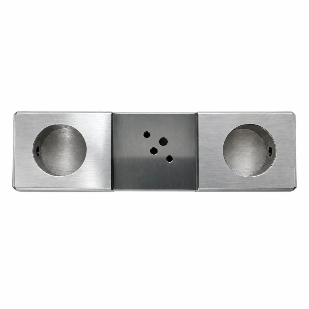
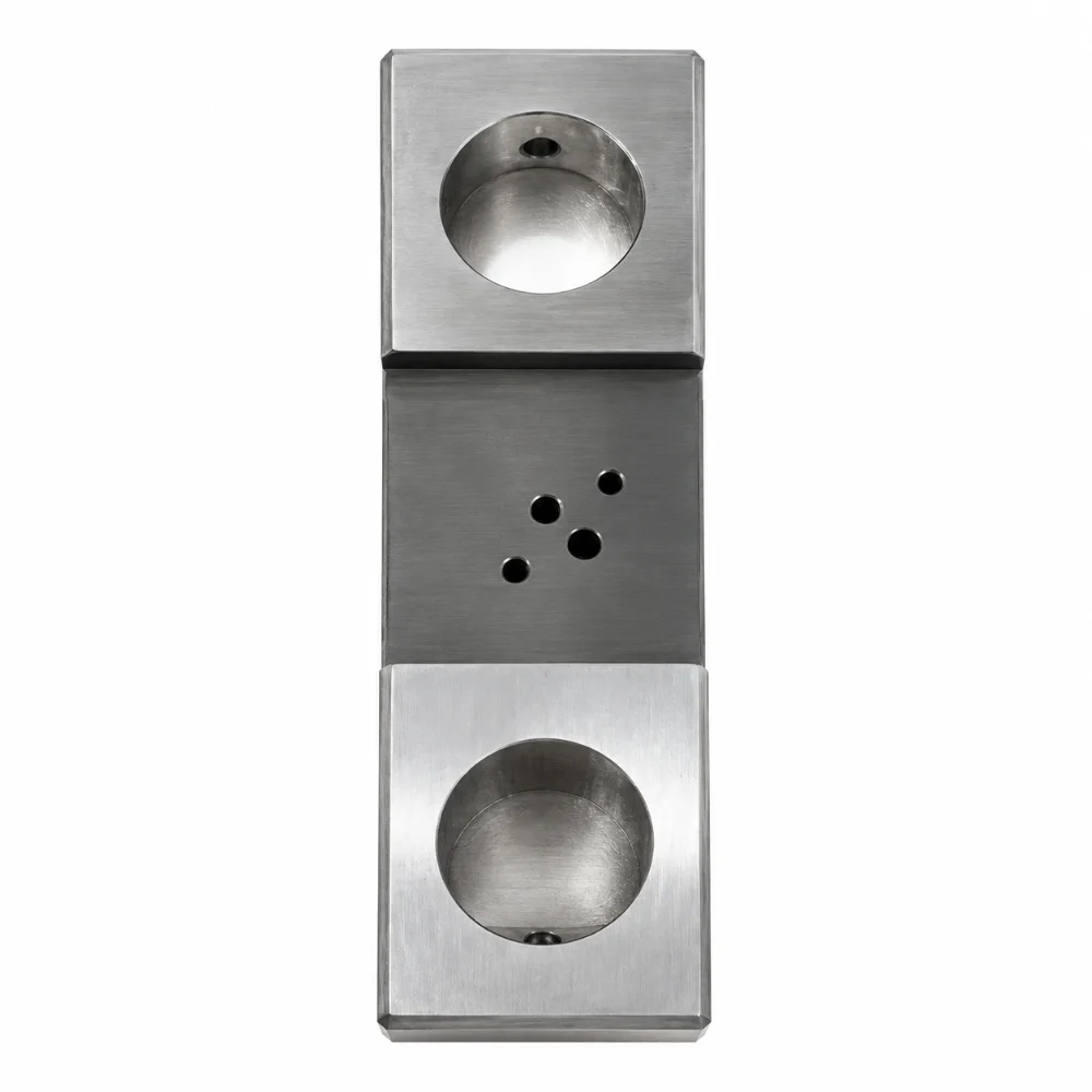
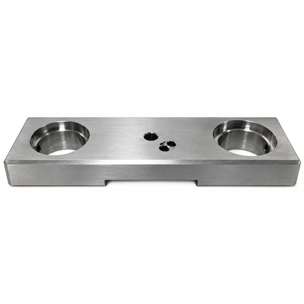
This 34CrNiMo6 steel CNC milling project involves a custom rectangular component featuring two large machined bores, multiple smaller holes, and a recessed central section.
The engineering drawing specifies EN 10083-3 steel and a hardness requirement of 500–600 HV10, making material condition and machining sequence important manufacturing considerations.
Unlike conventional low-hardness steel components, this prototype requires attention to cutting-tool selection, bore geometry, feature positioning, and potential dimensional changes associated with heat treatment.
-
Product Name: Custom CNC Machined 34CrNiMo6 Steel Block
-
Material: 34CrNiMo6 Alloy Steel (EN 10083-3)
-
Manufacturing Process: Precision CNC Milling, Drilling and Boring
-
Heat Treatment Specification: P30-026T
-
Hardness Requirement: 500–600 HV10 (Per Drawing)
-
Surface Finish: Machined Metal Finish
-
Main Features: Dual Large Bores, Precision Hole Pattern, Recessed Center and Underside Relief
-
Production Type: Custom CNC Machined Prototype
 Get Free Quote


CNC Milling Challenges of 34CrNiMo6 Alloy Steel
34CrNiMo6 is a chromium-nickel-molybdenum alloy steel used in applications where strength, toughness, and hardenability are important.
Compared with commonly machined aluminum alloys or relatively soft carbon steels, this material can require more careful control of cutting forces, tool wear, and machining temperatures, particularly after hardening.
The main engineering challenge is not simply removing material. It is producing several related features in a material that may undergo heat treatment while preserving the geometry needed for the final assembly.
Managing Machining and Heat Treatment
The drawing calls for a hardness range of 500–600 HV10.
This requirement must be considered when planning the machining sequence. Depending on the material's supplied condition and the required final dimensions, an appropriate strategy may involve rough machining before heat treatment and finishing critical features afterward.
Heat treatment can introduce dimensional changes, so sufficient machining allowance and an appropriate inspection plan may be necessary.
For this prototype, the exact manufacturing sequence should be determined from the complete engineering drawing and the customer's heat-treatment specification.
Machining Two Large Stepped Bores
The most prominent features are the two large circular bores positioned near opposite ends of the rectangular body.
Their machined entrances and internal profiles require controlled boring or interpolation operations to achieve the intended geometry.
Potential challenges include:
- Maintaining consistent bore diameters and profiles.
- Controlling the relative positions of the two bores.
- Preventing burr formation around bore openings.
- Managing cutting-tool wear when machining hardened steel.
An appropriate CNC milling process can combine roughing, circular interpolation, and finishing operations according to the drawing requirements.
Producing the Small Central Hole Pattern
The central section contains a group of smaller machined holes.
Compared with the larger bores, these features require smaller cutting tools and careful positioning. Hole diameter, drilling depth, entry condition, and location may all affect the fit of mating components.
For small holes in high-strength alloy steel, suitable cutting conditions and chip evacuation are important for reducing tool breakage and minimizing burrs.
Machining the Central Relief and External Edges
The component also includes a lowered central area and an underside relief feature visible in the photographs.
These features create different machining levels within a relatively simple rectangular outline.
Maintaining stable workholding while machining the recesses helps prevent unwanted movement and supports consistent relationships between the finished faces and bore features.
Suggested Manufacturing Approach
For components with this combination of material and geometry, the machining plan should be developed around the specified hardness condition and final assembly requirements.
| Manufacturing Stage | Engineering Consideration |
|---|---|
| Material Preparation | Verify 34CrNiMo6 material specification and supplied condition |
| Rough CNC Milling | Establish external geometry and reference surfaces |
| Bore Machining | Produce the two large bores and required internal profiles |
| Precision Drilling | Machine the smaller hole pattern according to the drawing |
| Heat Treatment Review | Determine the appropriate sequence for achieving 500–600 HV10 |
| Final Finishing | Finish critical dimensions where required by the process plan |
| Inspection | Verify geometry, bore dimensions, hole positions and specified hardness |
This is a proposed manufacturing approach for comparable parts, rather than a confirmed record of every operation performed on the photographed prototype.
Dimensional Inspection and Hardness Verification
High-hardness steel components require an inspection strategy that considers both geometry and material condition.
The photographed prototype has several features that deserve attention during inspection.
Bore Geometry: Internal diameters, bore profiles, and spacing should be checked using suitable measuring equipment.
Hole Positioning: The smaller hole pattern should be evaluated against the reference datums and positional requirements specified in the engineering drawing.
Flatness and Parallelism: Critical faces should be checked where these characteristics affect assembly or are explicitly controlled by the drawing.
Surface Condition: Bore edges, small-hole entrances, and milled recesses should be inspected for burrs or machining defects.
Hardness Verification: The drawing specifies 500–600 HV10. Compliance should be verified by an appropriate Vickers hardness test and recorded according to the customer's inspection requirements.
For further information, see Karry Precision's tolerance and quality control capabilities.
Why 34CrNiMo6 Was Specified for This Prototype
The engineering drawing identifies 34CrNiMo6 as the required material, although the final equipment application is not disclosed.
This alloy offers properties relevant to demanding mechanical components.
High Hardenability: Its alloying elements enable substantial hardening through suitable heat-treatment processes.
Strength and Toughness: With an appropriate heat-treatment condition, 34CrNiMo6 can provide a useful combination of mechanical strength and toughness.
Suitability for Custom Mechanical Components: The material is commonly considered for mechanically demanding parts such as shafts, gears, and structural components.
Defined Material Requirements: Manufacturing to EN 10083-3 helps establish a recognized material specification for purchasing and technical review.
Final material suitability must still be assessed against the actual operating loads, geometry, and application conditions.
Prototype Development and Potential Applications
The available drawing identifies this project as a prototype but does not confirm its final application.
Components with similar geometry and material requirements may be considered for industrial machinery, custom mounting assemblies, high-load mechanical equipment, or specialized positioning systems.
For prototype development, important engineering decisions include selecting machining datums, establishing the heat-treatment sequence, and determining which features require final finishing after hardening.
Karry Precision supports custom CNC machining for components manufactured from customer-supplied CAD models and technical drawings.




