
 Contact Us
 Home / /
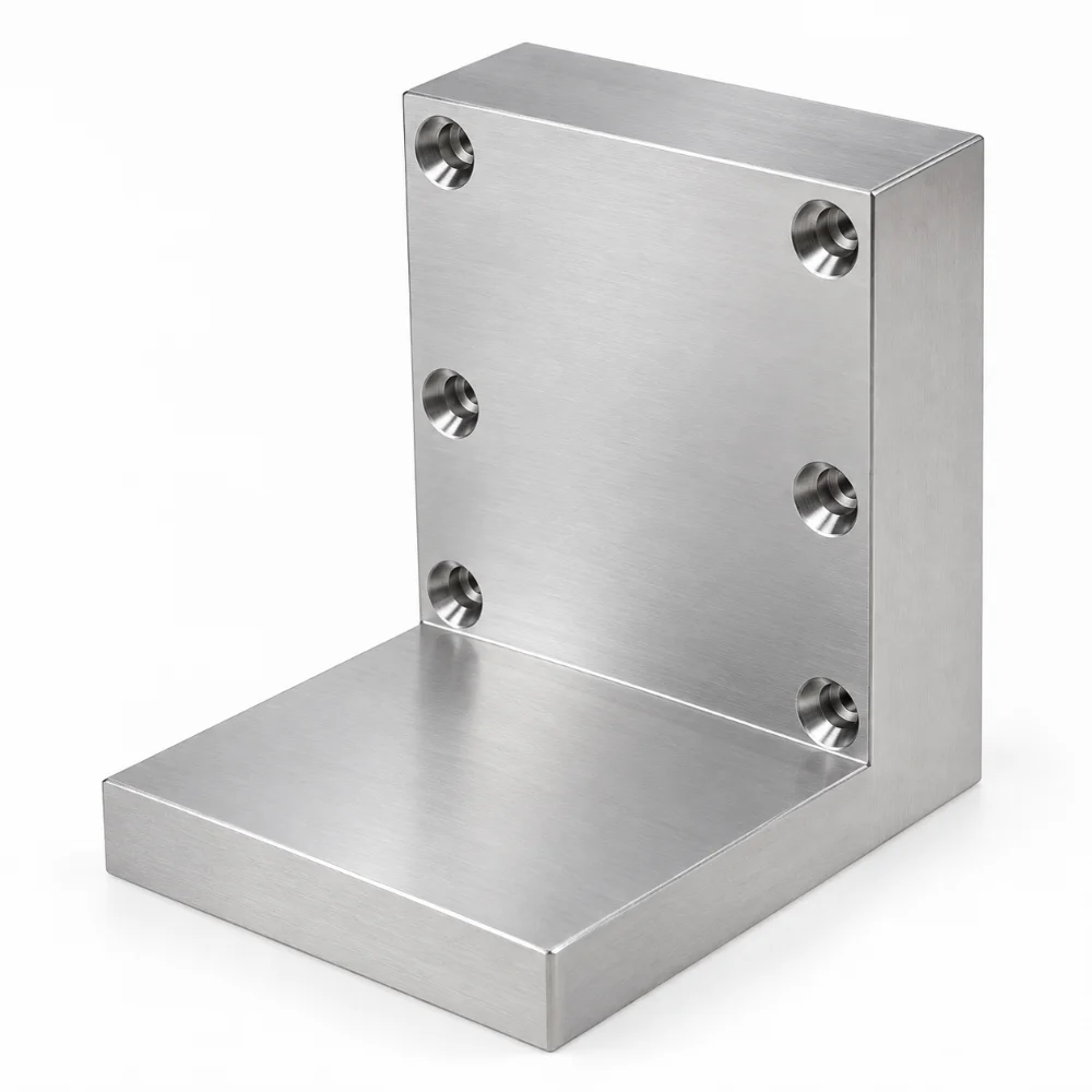


CNC Machined Aluminum Bracket for Motor Connection Block Assembly
The purpose of this CNC Machined Aluminum Bracket is to provide a rigid connection between motor-related components and their supporting structure. Its L-shaped geometry brings together a horizontal base and an upright mounting face, allowing the two interfaces to be positioned relative to one another.
What makes this component different from a conventional angle bracket is the arrangement of six recessed holes on the vertical face, combined with a substantial machined body. The relationship between the mounting face, hole positions, and perpendicular base is central to its assembly function.
- Product Name: CNC Machined Aluminum Bracket
- Component Description: Motor Connection Block
- Drawing Number: ET56955-00006, Rev. A
- Material Options: Aluminum 6061-T6/T651 or 2024-T4/T351
- Manufacturing Process: CNC Milling, Drilling and Hole Finishing
- Component Geometry: L-Shaped Block with Perpendicular Mounting Faces
- Mounting Features: Six Recessed Holes on the Upright Face
- Surface Treatment: Clear Chemical Conversion Coating
- Finish Specification: MIL-DTL-5541, Type II, Class 3
- Production Type: Custom Precision Machined Aluminum Component
 Get Free Quote


Why the Six-Hole Interface Matters
A hole pattern on a motor connection block is more than a collection of fastening points. Each hole must be positioned relative to the surrounding machined surfaces so that the corresponding hardware can be installed without unwanted interference.
The six visible holes are distributed in two vertical groups along the upright section. Their recessed openings introduce an additional machining consideration: the hole entry features and their positions must be consistent with the intended fastener arrangement.
Three aspects deserve particular attention:
- Hole-to-Hole Positioning: Maintaining the specified spacing between mounting locations.
- Mounting Face Alignment: Controlling the relationship between the upright face and horizontal base.
- Recessed Hole Geometry: Producing consistent hole entrances and seating features according to the final dimensions.
Unlike a simple flat mounting plate, this geometry requires dimensional control across two perpendicular functional surfaces.
Machining the L-Shaped Structure Without Losing Alignment
The manufacturing approach centers on establishing reliable reference surfaces before completing the mounting features.
The main external surfaces can be CNC milled to establish the required block geometry. Particular attention is given to the inside corner, the flatness of the mounting interfaces, and the thickness of the upright section.
Once suitable datum surfaces are established, the six mounting locations can be drilled and their recessed features machined in a controlled setup.
Where multiple setups are required, the relationship between the hole pattern and the previously machined reference faces must be preserved.
The internal L-shaped transition also requires careful tool access. Appropriate cutter selection and workholding help avoid unwanted marks on the functional surfaces.
Final edge finishing removes machining burrs without unnecessarily changing the specified hole geometry or contact surfaces.
Detailed Technical Specifications
| Parameter | Technical Specification |
|---|---|
| Product | CNC Machined Aluminum Bracket |
| Original Part Description | Motor Connection Block |
| Drawing Reference | ET56955-00006 |
| Revision | A |
| Material Specification | Aluminum Alloy 6061-T6/T651 or 2024-T4/T351 |
| General Linear Tolerances | .X ±0.2 mm / .XX ±0.10 mm, unless otherwise specified |
| Angular Tolerance | ±1°, unless otherwise specified |
| Main Structural Feature | Integral L-Shaped Mounting Geometry |
| Mounting Hole Configuration | Six Recessed Holes Visible on Upright Face |
| Main Machining Operations | CNC Milling, Drilling and Recessed-Hole Machining |
| Surface Treatment | Chemical Conversion Coating |
| Coating Standard | MIL-DTL-5541, Type II, Class 3, Clear |
| Surface Roughness | Not Specified in the Available Drawing Detail |
| Application | Motor Connection and Mechanical Mounting Assemblies |
| Manufacturing Type | Custom CNC Machined Aluminum Part |
Note: The material grades are alternatives permitted by the drawing, rather than a confirmed record of the alloy used for every finished component. Exact overall dimensions and individual hole specifications must be verified against the complete engineering drawing.
Material Selection and the Role of Clear Chemical Film
The design permits two aluminum alloy families: 6061 and 2024, in their specified tempers.
6061 is commonly selected for machined mechanical components because it provides a useful combination of machinability, strength, and corrosion resistance.
2024 offers higher strength in many applications but has different corrosion-resistance characteristics. The appropriate material depends on the mechanical and environmental requirements of the assembly.
The specified finish is a clear chemical conversion coating to MIL-DTL-5541, Type II, Class 3.
This treatment is distinct from decorative anodizing. It is often selected where corrosion protection and electrical-contact considerations are relevant, although the actual electrical requirements of this motor connection block are not established by the available drawing detail.
Maintaining clean, correctly prepared surfaces before conversion coating is important for achieving the specified finish.
Inspection Priorities for a Motor Connection Bracket
For this design, inspection should concentrate on the features that determine how the bracket fits into a larger assembly.
Perpendicularity of the Mounting Faces
The relationship between the horizontal and vertical surfaces should be checked against the applicable dimensional and geometric requirements. Errors in this relationship can affect the position of connected components.
Hole Pattern Location
The six mounting locations should be verified relative to the established reference surfaces. Hole diameter, position, and recessed geometry should follow the complete drawing.
Contact Surface Condition
The machined faces should be checked for burrs, damage, and unwanted raised material that could interfere with assembly.
Surface Treatment Verification
The clear conversion coating should be evaluated against the specified finish requirements, including applicable appearance and acceptance criteria.
These checks address the practical assembly risks of an L-shaped motor connection block rather than relying solely on an overall dimensional inspection.
Where This Type of Bracket Can Be Used
The drawing identifies the component as a motor connection block. Similar CNC machined aluminum brackets can be designed for motor-related installations and industrial mechanical assemblies.
Potential uses include motor mounting structures, automation equipment connection interfaces, machinery support assemblies, and custom positioning systems.
The suitability of any particular application depends on the loading conditions, fastening arrangement, mating components, and approved design requirements.
Frequently Asked Questions
1. What is the difference between a CNC machined aluminum bracket and a sheet metal bracket?
A CNC machined bracket can incorporate thicker sections, precision-machined mounting faces, recessed holes, and integrated geometry. A formed sheet metal bracket is generally more suitable for relatively thin, bent structures.
2. Why are multiple recessed mounting holes used in a motor connection block?
Multiple fastening locations can distribute attachment points across the mounting face. Recessed openings may provide clearance or seating space for selected fasteners, depending on the assembly design.
3. Can this aluminum motor connection bracket be made from 6061 or 2024?
Yes. The drawing lists 6061-T6/T651 and 2024-T4/T351 as material alternatives. Final material selection should follow the applicable engineering requirements.
4. What surface finish is specified for this component?
The drawing specifies a clear chemical conversion coating in accordance with MIL-DTL-5541, Type II, Class 3, rather than a decorative anodized finish.
5. Can the hole pattern and bracket dimensions be customized?
Yes. CNC machining allows the mounting-hole arrangement, overall dimensions, material selection, and surface finish to be developed around specific assembly requirements.




